Suppression of cladding mode loss in fiber amplifiers with distributed suppression of amplified spontaneous emission (ASE)

a fiber amplifier and cladding mode technology, applied in the field of fiber amplifiers with distributed suppression of amplified spontaneous emission, can solve the problems of introducing 1-2 db of additional insertion loss, difficult selection of fiber and fiber profile, and inconvenient cost-effectiveness, and achieve the effect of suppressing cladding mode loss

Inactive Publication Date: 2005-11-29
LUMENTUM OPERATIONS LLC
View PDF33 Cites 14 Cited by
  • Summary
  • Abstract
  • Description
  • Claims
  • Application Information

AI Technical Summary

Benefits of technology

[0015]It is a primary object of the present invention to provide a fiber amplifier with distributed suppression of amplified spontaneous emissions (ASE) above a certain cutoff wavelength and suppression of cladding mode loss at wavelengths shorter than the cutoff wavelength. In particular, it is an object of the invention to provide an Erbium-doped fiber amplifier having these capabilities.
[0016]Yet another object of the invention is to provide a method for designing fiber amplifiers with distributed ASE suppression and suppression of cladding mode loss below the cutoff wavelength.
[0017]These and numerous other advantages of the present invention will become apparent upon reading the following description.
[0018]The objects and advantages of the invention are achieved by a fiber amplifier with suppressed cladding mode loss. The fiber amplifier has an active core and a cladding surrounding the active core. An index profile is established in the active core and in the cladding such that the core exhibits a loss above a cutoff wavelength λc and positive gains in a short wavelength range below the cutoff wavelength λc. In accordance with the invention, the fiber amplifier has an arrangement for suppressing the coupling of a radiation in the short wavelength range between the active core and the cladding.
[0019]In some embodiments the arrangement for suppressing coupling between the active core and the cladding is a material distributed in the cladding. The material can be a scattering material or an absorbing material. For example, a rare earth element can be used as the absorbing material.
[0020]Preferably, the cladding has a depressed cladding having a depressed cladding cross-section and a refractive index n1 and a secondary cladding having a secondary cladding cross-section and a refractive index n2. The scattering or absorbing material is distributed in the secondary cladding. The radiation propagating in the active core occupies a mode having a mode diameter. The mode diameter extends from the active core into the cladding. It is important that the material be distributed outside the mode diameter of the radiation.

Problems solved by technology

In many fiber amplifiers ASE is a major obstacle to effective amplification of the desired signal and thus ASE has to be suppressed.
For example, in producing an EDFA for amplifying signals in the S-band the relatively high absorption losses and low gains over the S-band render the selection of fiber and fiber profile very difficult.
The problems are so severe that the prior art teaches interposition of external filters between EDFA sections to produce an S-band EDFA.
Unfortunately, Payne's, Ishikawa's and Srivastava's methods are relatively complicated and not cost-effective, as they require a number of filters.
Also, each of the ASE suppressing filters used by either method introduces an additional insertion loss of 1-2 dB.
Moreover, they observe that depressed-index claddings produce high losses to the fundamental mode at long wavelengths.
The longer the wavelength, the deeper its evanescent field penetrates out of the core of the fiber, and the more likely the radiation at that wavelength will be lost from the core of the bent fiber.
Unfortunately, the bending of profiled fibers is not a very controllable and reproducible manner of achieving well-defined cutoff losses.
Hence, this approach to obtaining high attenuation rates is not practical in manufacturing.
This effect, also known as cladding mode resonance, produces artifacts or cladding mode coupling losses in the short wavelength range of interest where the signal is to be amplified.
Cladding mode loss is a problem encountered in fiber Bragg gratings.
Unfortunately, the approaches which are useful in suppressing cladding mode losses and avoiding cladding mode resonance in fiber Bragg gratings can not be applied to fiber amplifiers.

Method used


Image

  • Suppression of cladding mode loss in fiber amplifiers with distributed suppression of amplified spontaneous emission (ASE)
  • Suppression of cladding mode loss in fiber amplifiers with distributed suppression of amplified spontaneous emission (ASE)
  • Suppression of cladding mode loss in fiber amplifiers with distributed suppression of amplified spontaneous emission (ASE)

Examples


Embodiment Construction

and the preferred and alternative embodiments is presented below in reference to the attached drawing figures.

BRIEF DESCRIPTION OF THE FIGURES

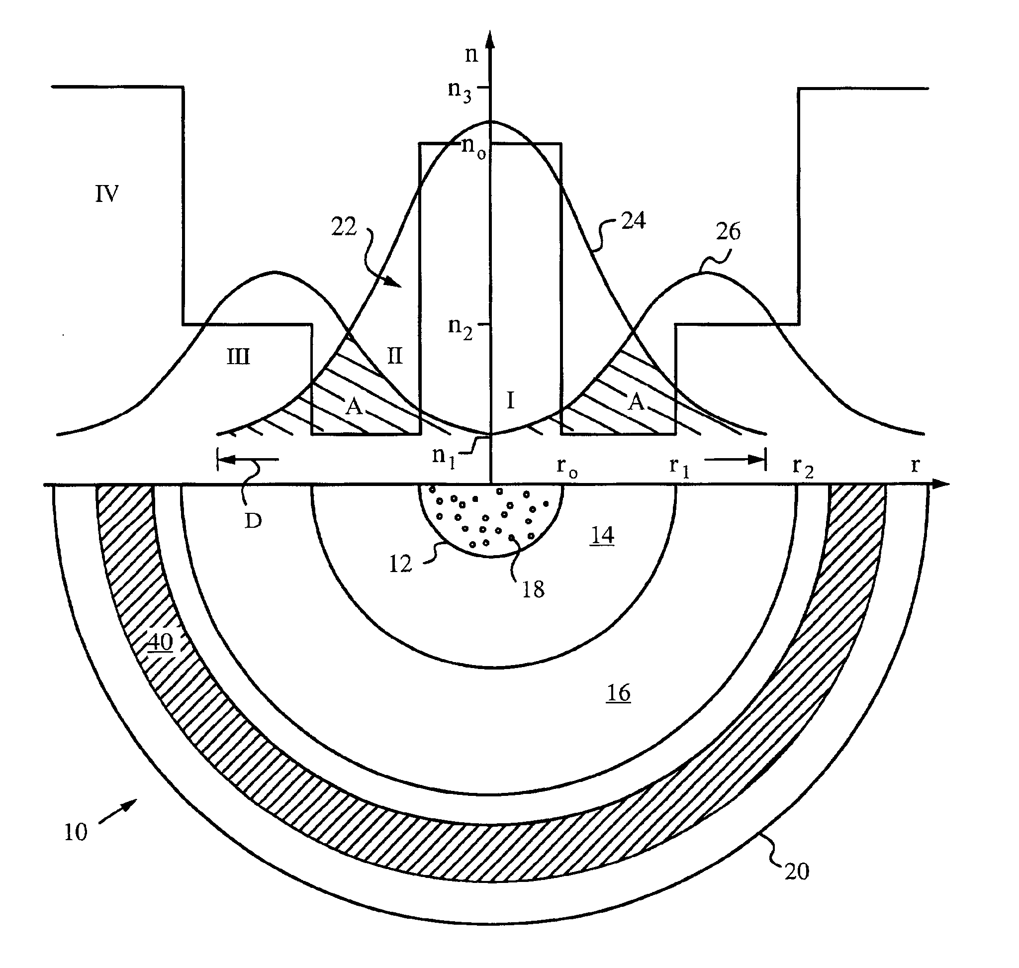
[0025]FIG. 1 is a diagram illustrating a partial cross-section of a fiber amplifier in accordance with the invention and illustrating a core mode and a cladding mode.

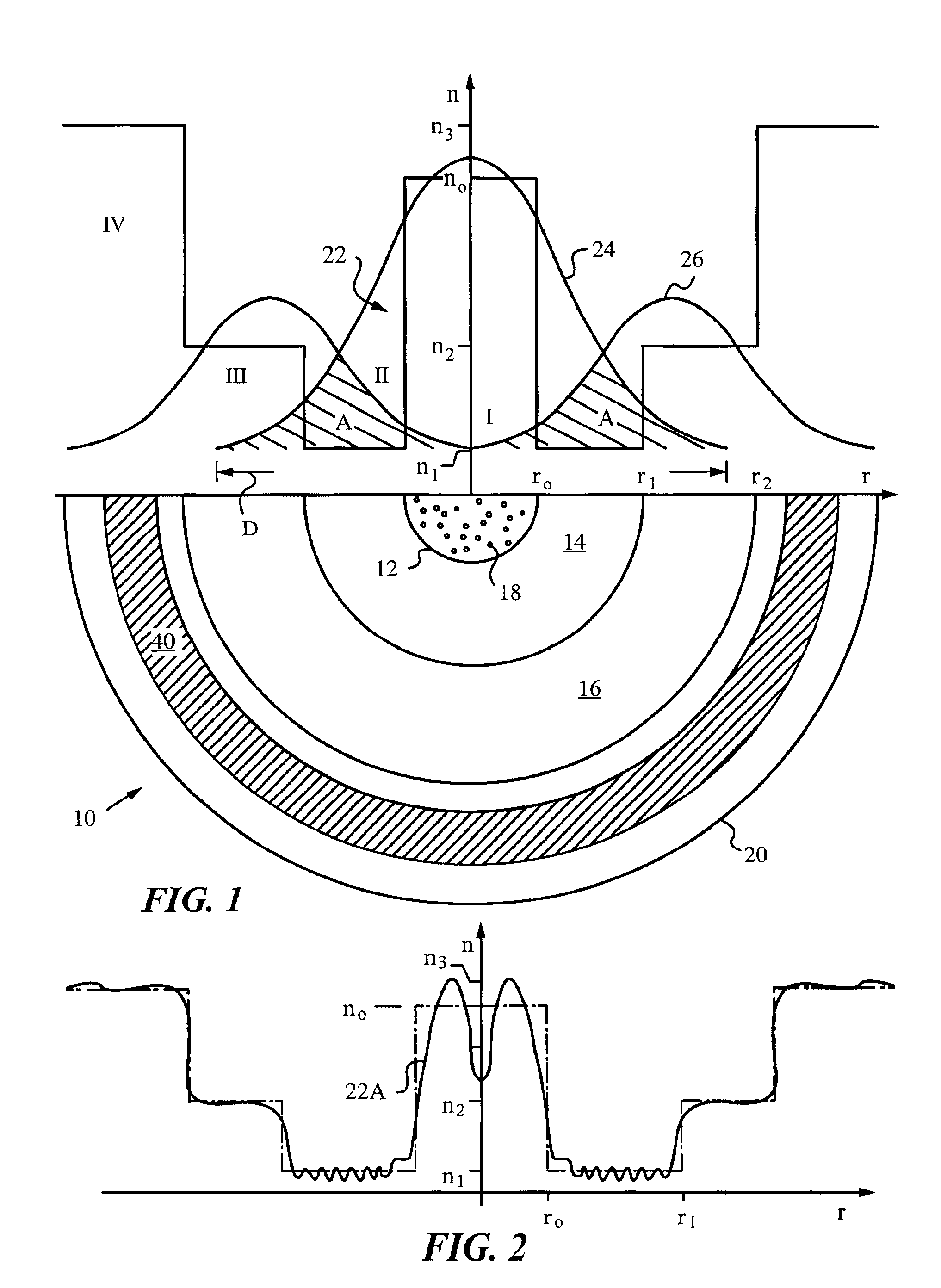
[0026]FIG. 2 is a graph illustrating a typical index profile in the fiber of FIG. 1.

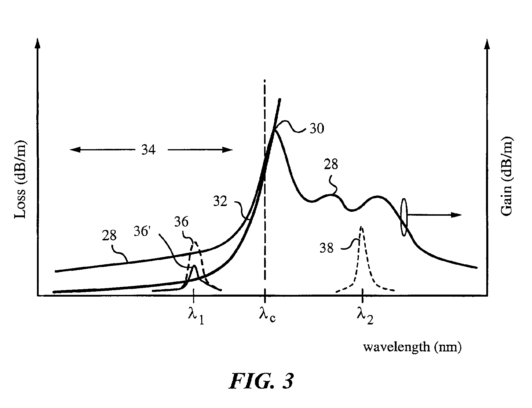
[0027]FIG. 3 is a graph illustrating the effects of cladding mode losses in the fiber of FIG. 1.

[0028]FIG. 4 are graphs illustrating the effects of an absorbing polymer material embedded in outer cladding of the fiber of FIG. 1.

[0029]FIG. 5 is a diagram illustrating a partial cross-section of another fiber amplifier according to the invention.

[0030]FIG. 6 is a graph illustrating the phase-matching condition between core modes and cladding modes in the fiber amplifier of FIG. 5.

[0031]FIG. 7 are graphs of power levels of radiation in core mode and cladding mode.

[0032]FIGS. 8A&B are graphs illustratin...


PUM


Abstract

A fiber amplifier in which the active core is surrounded by a cladding and coupling of radiation between a core mode and cladding modes is suppressed to minimize cladding mode losses in a short wavelength range. An index profile is established in the active core and in the cladding such that the core exhibits a loss above a cutoff wavelength λc and positive gains in the short wavelength range below the cutoff wavelength λc. Suppression of cladding mode losses is achieved by an arrangement for suppressing the coupling of radiation in the short wavelength range between a core mode supported the active core and a cladding mode supported by the cladding. The arrangement for suppressing can include an absorbing material or a scattering material distributed in the cladding. The arrangement for suppressing can include a non-phase-matched length section of the fiber amplifier in which the core mode and the cladding modes are not phase matched.

Description

RELATED APPLICATIONS[0001]This application is related to U.S. application Ser. No. 09 / 825,148 filed on Apr. 2, 2001, now U.S. Pat. No. 6,563,995, and to U.S. application Ser. No. 10 / 095,303 filed on Mar. 8, 2002.FIELD OF THE INVENTION[0002]The present invention relates generally to fiber amplifiers in fibers with distributed suppression of ASE where coupling between a core mode and cladding modes is suppressed to improve performance.BACKGROUND OF THE INVENTION[0003]The problem of amplifying optical signals for long distance transmission was successfully addressed by the development of Erbium doped fiber amplifiers (EDFAs). An EDFA consists of a length of silica fiber with an active core doped with ionized atoms (Er3+) of the rare earth element Erbium. The fiber is pumped with a laser at a wavelength of 980 nm or 1480 nm. The doped, pumped fiber is optically coupled with the transmission fiber so that the input signal is combined with the pump signal in the doped fiber. An isolator i...

Claims


Application Information

Patent Timeline
Patent Type & Authority Patents(United States)
IPC IPC(8): H01S3/067H01S3/08H01S3/16
CPCH01S3/06754H01S3/06712H01S3/06729H01S3/1608H01S3/1616H01S2301/02
Inventor ARBORE, MARK A.
Owner LUMENTUM OPERATIONS LLC
Why Eureka
Try Eureka