Testing device driver hardening

a technology for hardening and device drivers, applied in error detection/correction, instruments, computing, etc., can solve problems such as system crash, $50 pci card can crash a $500,000 server, and not always, however, an acceptable approach, and achieve the effect of facilitating the construction of a hardening driver test mechanism

Inactive Publication Date: 2005-11-29
ORACLE INT CORP
View PDF6 Cites 52 Cited by
  • Summary
  • Abstract
  • Description
  • Claims
  • Application Information

AI Technical Summary

Benefits of technology

[0016]An embodiment of the invention overcomes the problem that it is not normally possible to have sufficient access to the hardware design of a device to be able to inject a suitable varied range of faults. Modern device drivers access hardware through a set of specific functions. The use of these functions within a compliant driver can facilitate the construction of a hardened driver test mechanism.
[0017]The present test mechanism allows a test engineer to specify a reference to (for example) a specific device, a specific register set on that device, an offset range, a data mask value, a logical / arithmetic operator (=, NOT, AND, OR, XOR, +, −) and an access count. Intercept routines then check each use by the device driver interface of the device access calls to see if it is within the specified parameters. A count is decremented on each matching occurrence. When the count has expired the data read can be operated upon by a pre-specified operator and operand. This allows a test mechanism to introduce a vast range of different faults.

Problems solved by technology

A faulty device can and often will cause the system to crash.
As a result, a $50 PCI card can crash a $500,000 server.
This is not always, however, an acceptable approach.
Hardened device drivers reduce the potential for defective devices to cause a totally disruptive system loss.
It may attempt this in a range of devious and inventive ways.
It may refuse to respond to accesses, so causing bus time-out exceptions.
It may attempt to dupe the system kernel into undertaking suicidal action.
It may corrupt the data which it delivers.
However, this is an expensive and time consuming task, and may in the end only give limited ability to test possible faults.

Method used


Image

  • Testing device driver hardening
  • Testing device driver hardening
  • Testing device driver hardening

Examples


Embodiment Construction

[0031]An embodiment of the present invention will be described in the context of a Peripheral Component Interconnect (PCI) local bus. It should be noted that the application of an embodiment of the invention is not limited to a PCI local bus architecture, but could be used with other bus architectures.

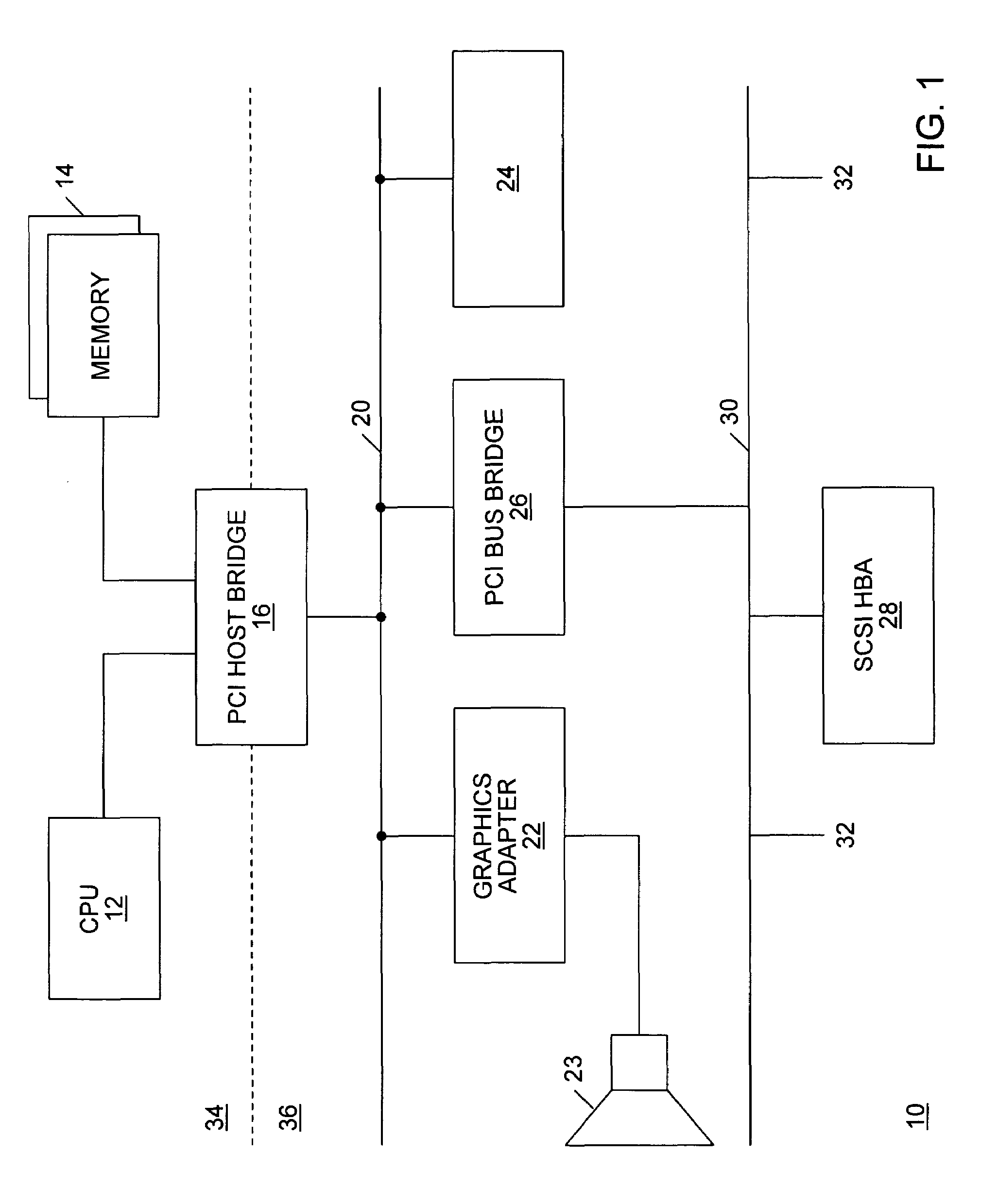
[0032]FIG. 1 is a schematic overview of a computer system including a PCI local bus system. A PCI bus usually resides on the system board of a computer system. As shown in FIG. 1, a processor 12, main memory 14 and a PCI bus 20 are connected through a PCI host bridge 16. Through a cascade of PCI bus bridges (of which only one PCI bus bridge 26 is shown), a tree structure of interconnected I / O buses is supported. In other words, subordinate PCI bus bridges can be extended underneath the PCI host bridge 16 to allow a single bus system to be expanded into a complex system with multiple secondary buses, such as the secondary bus 30. PCI devices can be connected to one of these secondary bu...


PUM


Abstract

A test mechanism for testing device driver hardening includes an intercept mechanism for intercepting device driver access calls from a device driver under test and an interface for configuring the intercept mechanism to inject faults according to a determined test pattern. This mechanism enables the arbitrary introduction of typical faults. These faults may be introduced totally asynchronously and so emulate real life. A test harness module can be linked in to a test build of the driver. The test harness can intercept all of the device access calls. It mimics the normal function of these calls accessing the offset address and propagating the appropriate data. A test application is able to interpret a test script and to compare device driver responses to injected faults.

Description

BACKGROUND OF THE INVENTION[0001]This invention relates to the testing of device drivers, and in particular to testing the hardening of device drivers.[0002]Traditionally devices drivers have been written with their emphasis on good performance and correct operation in the absence of faults. Looking in driver writing guides and training material there is little (if any) mention made of how to deal with faulty hardware devices. A faulty device can and often will cause the system to crash. As a result, a $50 PCI card can crash a $500,000 server.[0003]A standard approach to improving system availability in the face of I / O faults is to have the system crash, then reboot and configure the faulty device out of the system. This is not always, however, an acceptable approach.[0004]A much better approach is to modify drivers to survive I / O faults and reconfigure the device without a reboot. A device driver which has been designed to be resilient against such failures is known as a “hardened”...

Claims


Application Information

Patent Timeline
Patent Type & Authority Patents(United States)
IPC IPC(8): G06F11/36
CPCG06F11/3672
Inventor HANSON, STEPHEN RICHARDRADLEY, EDWARD JAMES
Owner ORACLE INT CORP
Why Eureka
Try Eureka