Method for connecting microchips to an antenna arranged on a support strip for producing a transponder

a technology of microchips and antennas, applied in the direction of decorative surface effects, resistance welding apparatus, decorative arts, etc., can solve the problem of significant increase in manufacturing speed

Inactive Publication Date: 2005-12-06
MUEHLBAUEHR AG
View PDF15 Cites 33 Cited by
  • Summary
  • Abstract
  • Description
  • Claims
  • Application Information

AI Technical Summary

Benefits of technology

[0005]The object of this invention is to further develop a method of the type mentioned at the beginning which enables transponders to be manufactured more simply, faster and, above all, more economically.
[0007]Shifting the bonding process to a preceding process has the advantage that the chip module produced in this manner can be applied substantially quicker and easier to the first carrier tape fitted with the antennas. It is possible to solder or crimp the chip module to the antenna which, on one hand, is substantially quicker and, on the other hand, demands less precision than a bonding process. With the method according to the invention, the manufacturing speed can be further increased in that both carrier tapes are unwound from the reel and brought one over the other and at the time of placement of the chip module on the first carrier tape, the speeds of both carrier tapes are adjusted. Consequently, it is not necessary that the carrier tapes are at standstill when the chip module is connected to an antenna. The process can therefore run continuously, resulting in a significant increase in the manufacturing speed. In this case it is not that the preceding bond process leads to an overall slowing down of the manufacturing process at another point. It is rather that the packaging of the micro-chip into a chip module within the framework of a preceding bonding process is substantially easier to implement than the bonding of a micro-chip to an antenna. Furthermore, the packaging of the micro-chip into a chip module can occur at a central point, for example, at the chip manufacturer's premises, so that the procurement by the transponder manufacturer of an expensive bonder requiring highly qualified operating personnel is not needed.
[0010]It is advantageous if the soldering of the chip module to the antenna occurs using a laser beam.

Problems solved by technology

The process can therefore run continuously, resulting in a significant increase in the manufacturing speed.

Method used


Image

  • Method for connecting microchips to an antenna arranged on a support strip for producing a transponder
  • Method for connecting microchips to an antenna arranged on a support strip for producing a transponder
  • Method for connecting microchips to an antenna arranged on a support strip for producing a transponder

Examples


Embodiment Construction

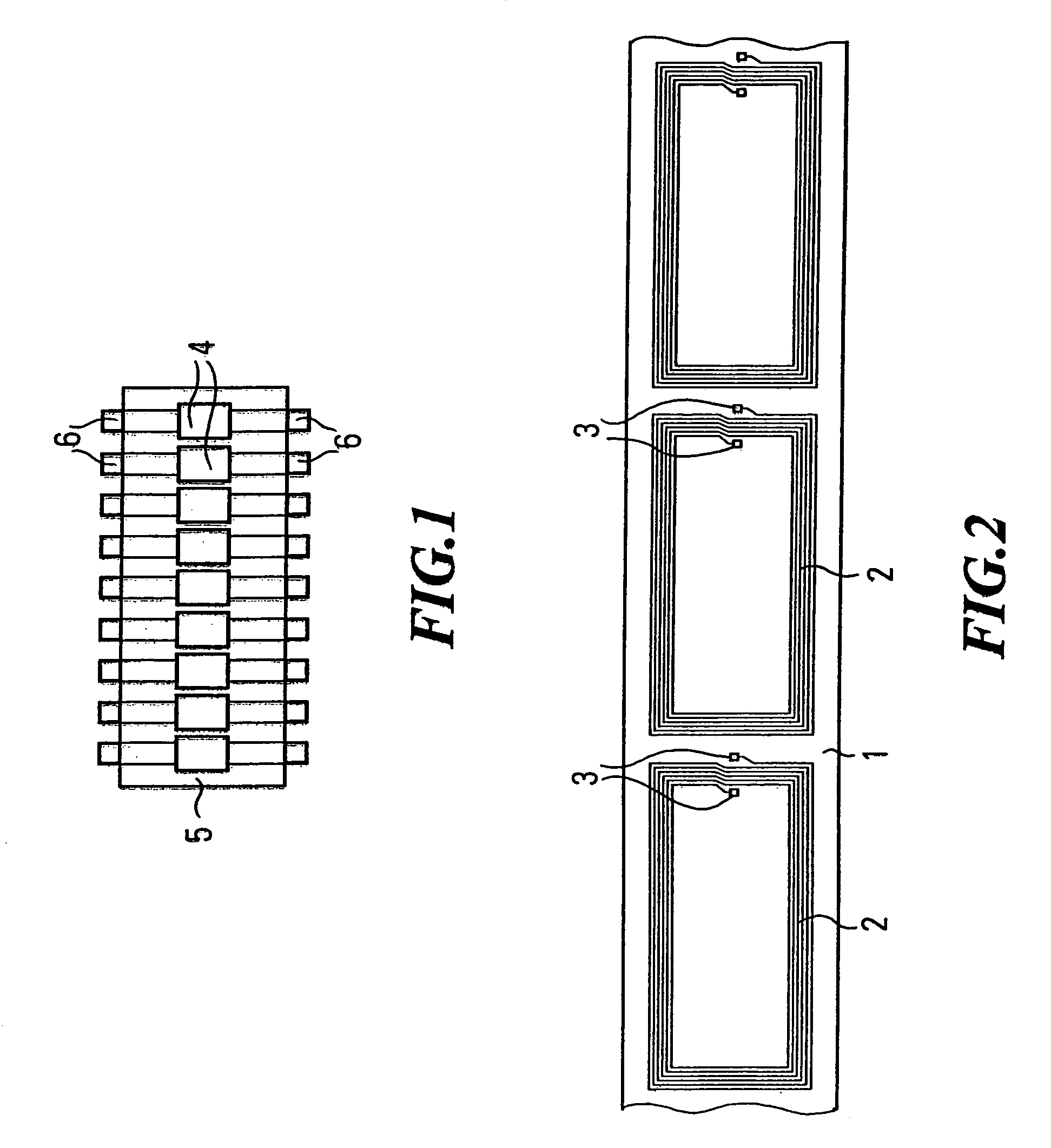
[0017]FIG. 1 shows a first carrier tape 1 onto which coils 2 have been applied as antennas. Here, antennas manufactured by electroplated deposition are involved. The coils 2 exhibit two terminals 3 for a chip module.

[0018]These chip modules 4 are shown in FIG. 2. They are held closely one behind the other on a second carrier tape 5. The chip modules are packaged by a preceding bonding process into a chip case shown in FIG. 2. This case exhibits two galvanised terminal pads 6, the spacing of which corresponds to the terminals of the rectangular coils 2.

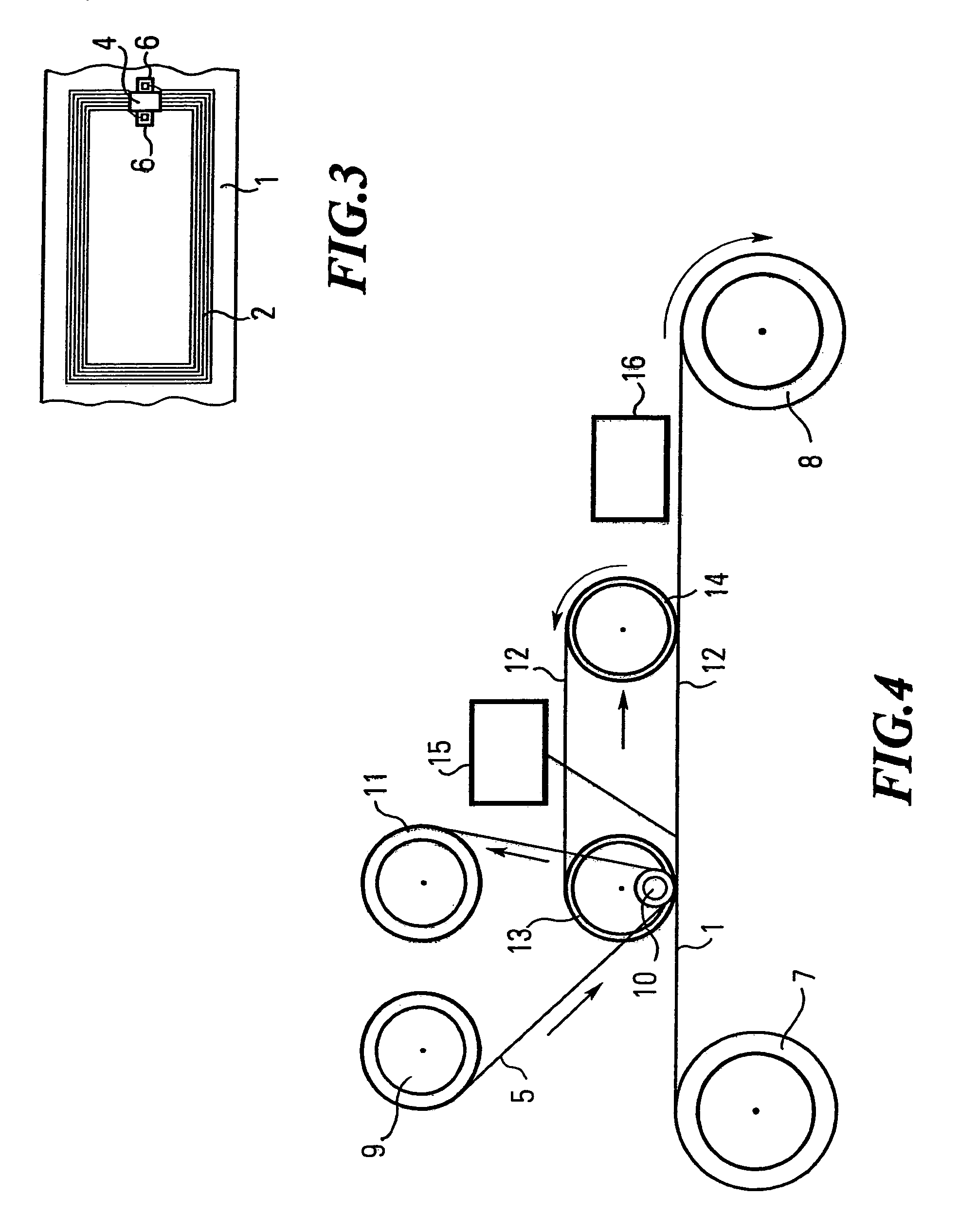
[0019]FIG. 3 shows a carrier tape 1 with a rectangular coil 2 which has already been complemented with a chip module 4. The chip module 4 has been soldered to the terminals 3 through its terminal pads 6.

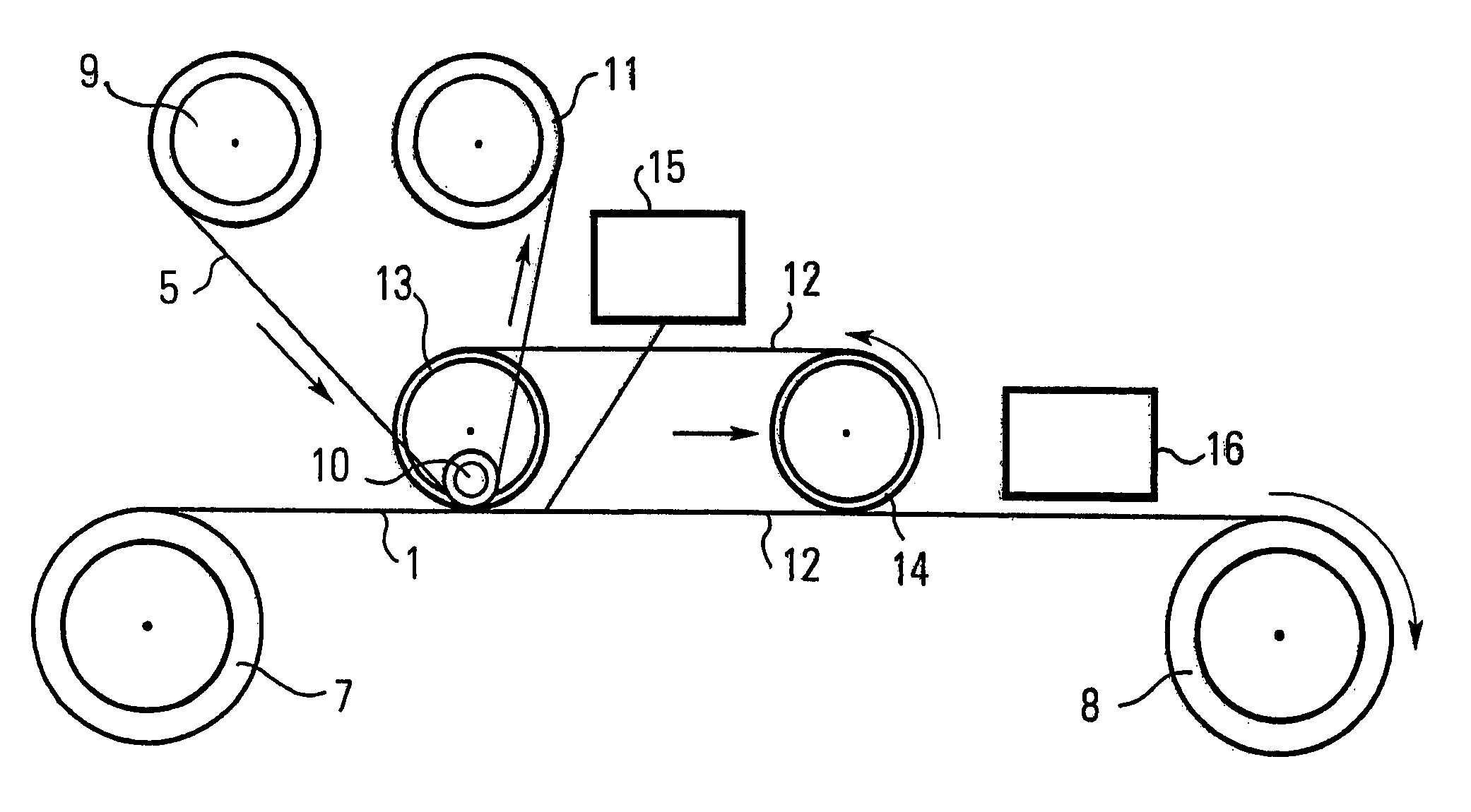
[0020]In the following the manufacturing method is explained in more detail based on FIG. 4.

[0021]The first carrier tape 1 is rolled onto an input spool 7 and is unrolled from it and wound onto a finish spool 8 after the connection proc...


PUM

PropertyMeasurementUnit
speedaaaaaaaaaa
electrical connectionaaaaaaaaaa
sizeaaaaaaaaaa

Abstract

The invention relates to a method of connecting micro-chip modules to antennas arranged on a first carrier tape for the manufacture of transponders. The method is characterised in that the micro-chips are packaged in a preceding bonding process to form a chip module with electrical terminals and are applied to a second carrier tape. The two carrier tapes are wound off a reel and brought one above the other, whereby the chip modules are removed from the second carrier tape and placed at a predetermined point on the first carrier tape. This method facilitates a continuous manufacturing process which is particularly economical and particularly fast.

Description

BACKGROUND OF THE INVENTION[0001]1. Field of the Invention[0002]The invention relates to a method of connecting micro-chips to antennas arranged on a first carrier tape for the manufacture of a transponder.[0003]2. Description of the Related Art[0004]This type of transponder, which, for example, are used for smart labels or smart cards, exhibit a flat antenna coil, which is fitted with two connections. The antennas can be manufactured from various materials, such as, for example, copper, aluminium, silver conducting paste, etc. The size of the antennas can vary depending on the application. With currently employed manufacturing methods the flat antenna coils are applied to a carrier tape which is wound onto a reel. Up to the present time, the micro-chips have been connected to the antennas on the carder tape through a complex bonding process. This requires that the carrier tape exhibiting the antennas passes via an indexer and is at standstill during the bonding process. Apart from ...

Claims


Application Information

Patent Timeline
Patent Type & Authority Patents(United States)
IPC IPC(8): G06K19/077H01L21/60
CPCG06K19/07718G06K19/07749G06K19/0775G06K19/077
Inventor BROD, VOLKEROVERMEYER, LUDGER
Owner MUEHLBAUEHR AG
Why Eureka
Try Eureka