Power-on reset circuit

a power-on reset and circuit technology, applied in the direction of pulse automatic control, electronic switching, pulse technique, etc., can solve the problems of unstable reset pulse, ungenerated reset pulse, disabling circuit to normally operate, etc., and achieve low power consumption and avoid unnecessary power consumption.

Inactive Publication Date: 2005-12-06
SHARP KK
View PDF6 Cites 33 Cited by
  • Summary
  • Abstract
  • Description
  • Claims
  • Application Information

AI Technical Summary

Benefits of technology

[0016]By way of a second feature, according to the POR circuit of the invention, the reset pulse generation circuit outputs the second output voltage to the output node and reduces the set value of the charge level. More specifically, in the POR circuit according to the second feature, the reset pulse generation circuit comprises an inverter circuit in an initial stage for inputting the charge level of the capacitor as an input voltage and outputs a negation logic level thereof, and a transistor for imparting hysteresis characteristics to the inverter circuit.
[0017]According to the POR circuit according to the second feature of the invention, ordinarily a plurality of circuits synchronously starts a reset operation after the reset pulse has once shifted the second output voltage. As such, although a case can take place in which unserious apparent variations in the power supply voltage are caused by AC noise generated by parasitic induction components in the power supply and ground line, the invention can prevent a case where the output of the reset pulse is unstabilized by the variations in the power supply voltage. More specifically, the output of the reset pulse once shifted to the second output voltage returns to the first output voltage, therefore enabling occurrence of, for example, chattering between the first output voltage and the second output voltage to be prevented. The feature is specifically effective when boosting of the power supply voltage is slow.
[0019]According to the third feature, in the POR circuit of the invention, DC current paths occurring in the reset pulse generation stage are blocked after the reset pulse generation. As such, the DC current is consumed only by necessity in an initial power-on stage, unnecessary power consumption can be avoided in a long period of time after the reset pulse generation. Consequently, low power consumption can be implemented overall in the circuit.

Problems solved by technology

However, in a POR circuit of the above-described type composed only of such the capacitor charge circuit, a problem occurs in that a reset pulse is not generated when a boosting speed rate of the power supply voltage is later than a charge time constant of the capacitor.
Since discharging means of the capacitor is not provided, the capacitor cannot securely be discharged, thereby disabling the circuit to normally operate.
However, the POR circuit according to the conventional technique 2 has a problem in that when variations take place in the voltage of the node N70 in the vicinity of a threshold voltage of the inverter 75, a stable reset pulse is not output.

Method used


Image

  • Power-on reset circuit
  • Power-on reset circuit
  • Power-on reset circuit

Examples


embodiment

Preferred Embodiment

[0025]Referring to the accompanying drawings, an embodiment of a POR circuit of the invention (which hereafter will also be referred to as an “inventive circuit”) will be described hereinbelow.

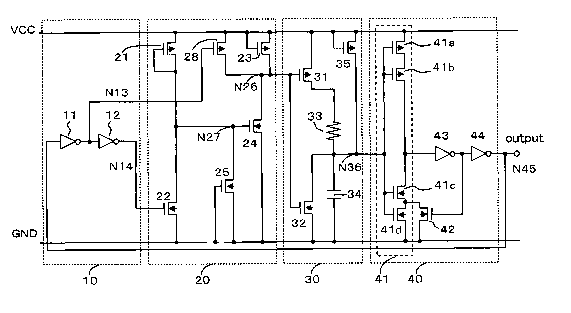
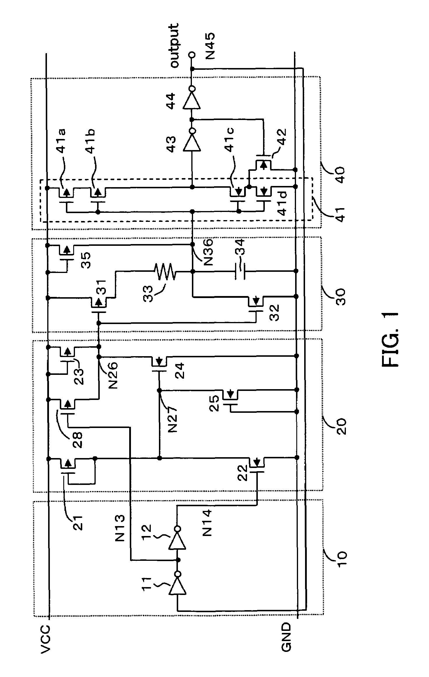
[0026]Referring to FIG. 1, the inventive circuit is composed of a power supply voltage detection circuit 20, a capacitor charge / discharge circuit 30, a reset pulse generation circuit 40, and a power reduction circuit 10.

[0027]The power supply voltage detection circuit 20 detects a rise of a power supply voltage Vcc to a predetermined voltage V or higher and then causes a logical level of a first internal node N26 to change from a high level (first level) to a low level (second level). More specifically, as shown in FIG. 1, the power supply voltage detection circuit 20 is composed of three P-type MOSFETs (each of which hereinbelow will be referred to as a “PMOS”) 21, 23, and 28 and three N-type MOSFETs (each of which hereinbelow will be referred to as a “NMOS”) 22, 24, and 2...


PUM


Abstract

A power-on reset circuit comprises a power supply voltage detection circuit that detects a rise of a power supply voltage and that changes a logic level of a first internal node; a capacitor charge / discharge circuit that charges and discharges a capacitor according to the first internal node level and that in an event that the power supply voltage is reduced, discharges the capacitor to follow the event; and a reset pulse generation circuit that before the power supply voltage rises higher than the predetermined voltage, outputs a first output voltage to an output node and that after the power supply voltage has risen higher than the predetermined voltage, outputs a second output voltage to the output node upon detecting that a charge level of the capacitor has become higher than a charge level detection voltage.

Description

[0001]This Non-provisional application claims priority under 35 U.S.C. §119(a) on Patent Application No(s). 2003-117798 filed in Japan on Apr. 23, 2003, the entire contents of which are hereby incorporated by reference.BACKGROUND OF THE INVENTION[0002]1. Field of the Invention[0003]The present invention relates to a power-on reset circuit (which hereinbelow will be referred to as a “POR circuit”) for generating a reset pulse by a sensing a power supply voltage rise at a power-on time. More particularly, the invention relates to a POR circuit to be provided to reset another circuit within a same integrated circuit in a semiconductor integrated circuit.[0004]2. Description of Related Art[0005]Conventional POR circuits have a capacitor charge circuit composed of a charging capacitor and a resistor or a constant current source, and outputs a reset pulse at a power-on time. However, in a POR circuit of the above-described type composed only of such the capacitor charge circuit, a problem...

Claims


Application Information

Patent Timeline
Patent Type & Authority Patents(United States)
IPC IPC(8): H03K17/22H03K17/687
CPCH03K17/223
Inventor AKAMATSU, TETSUYADOI, HIROKIINAMORI, MASANORI
Owner SHARP KK
Why Eureka
Try Eureka