Ultra-broadband antenna incorporated into a garment

a technology of ultra-broadband antennas and garments, applied in the field of ultra-broadband antennas, can solve the problems of low gain of frequencies higher than 200 mhz, too small for efficient operation, etc., and achieve the effect of reducing the energy that flows into the body

Inactive Publication Date: 2005-12-06
NAVY SEC OF THE UNITED STATES
View PDF8 Cites 40 Cited by
  • Summary
  • Abstract
  • Description
  • Claims
  • Application Information

AI Technical Summary

Benefits of technology

[0008]On the inside layer of first and second garments, insulating material is disposed within first and second antennas. Insulating material is disposed in pockets sewn in the regions of the RF feeds. Insulating material is also disposed over the length and width of the gap that separates first and second RF elements, third and fourth RF elements, and fifth and sixth RF elements. By way of example, insulating material may be made of material generally called tubular composites. To fabricate these tubular composites, cylinders of copper and / or ferrite tubules, 25 microns long and 1 micron in diameter, are mixed in controlled amounts with polyurethane or other polymers, which then solidify into a rubber-like sheet. Insulating material reduces the energy that flows into the body and shields the wearer from electromagnetic radiation. Disposed over the length and width of gaps that separate the RF elements, insulating material also reflects energy without shorting first and second antennas.
[0009]Use of multiple antennas with a diplexer allows optimization of each antenna within a narrower frequency range. A diplexer provides a passive means, i.e., no operator intervention required, to route signals from a radio to the appropriate antenna for efficient operation. A single-pole, two-throw switch is an example of an active means, i.e., requires operator intervention, of directing the signal to the appropriate antenna.

Problems solved by technology

However, the gain for frequencies higher than 200 MHz was often less than −20 dBi, too small for efficient operation.

Method used


Image

  • Ultra-broadband antenna incorporated into a garment
  • Ultra-broadband antenna incorporated into a garment
  • Ultra-broadband antenna incorporated into a garment

Examples


Embodiment Construction

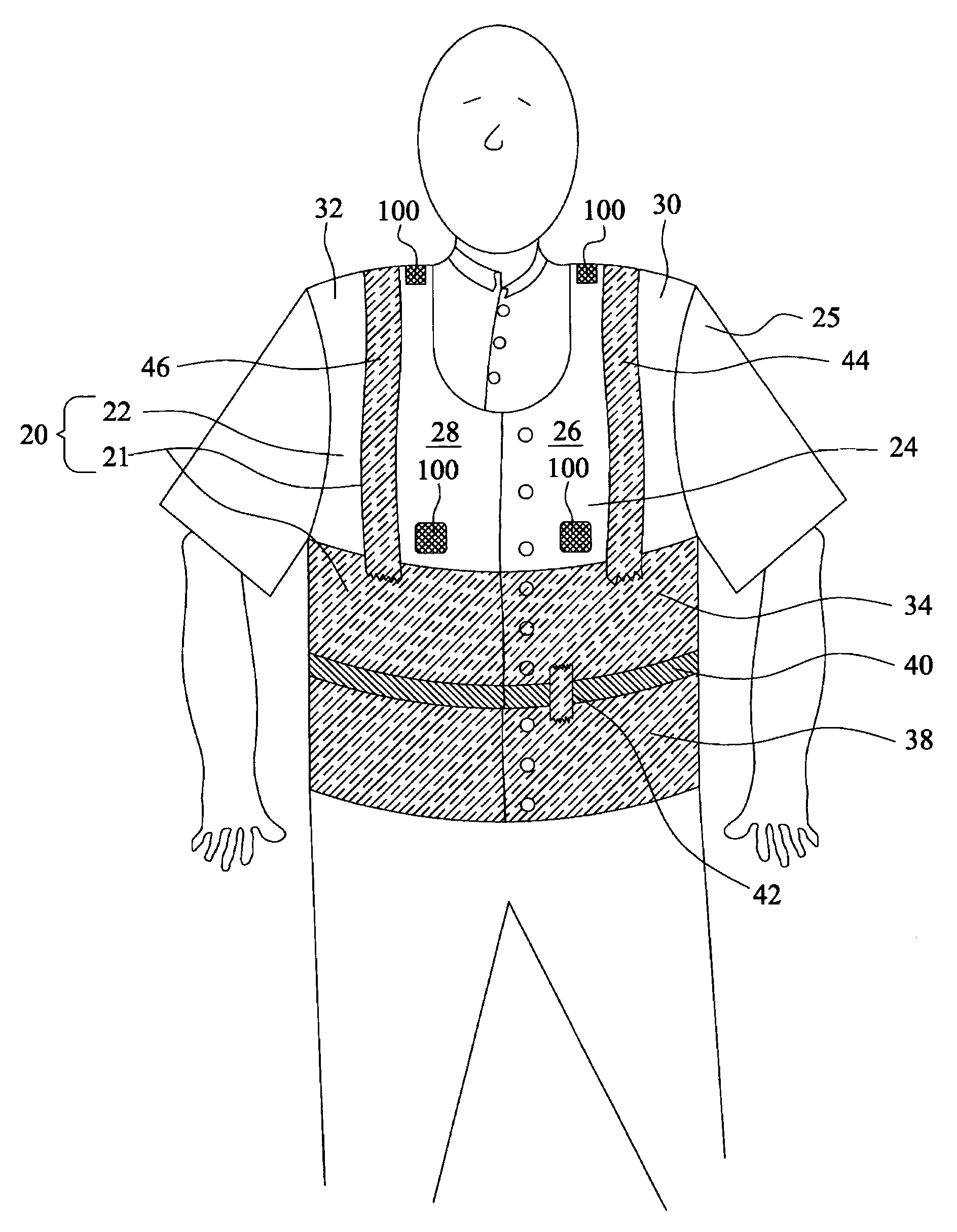
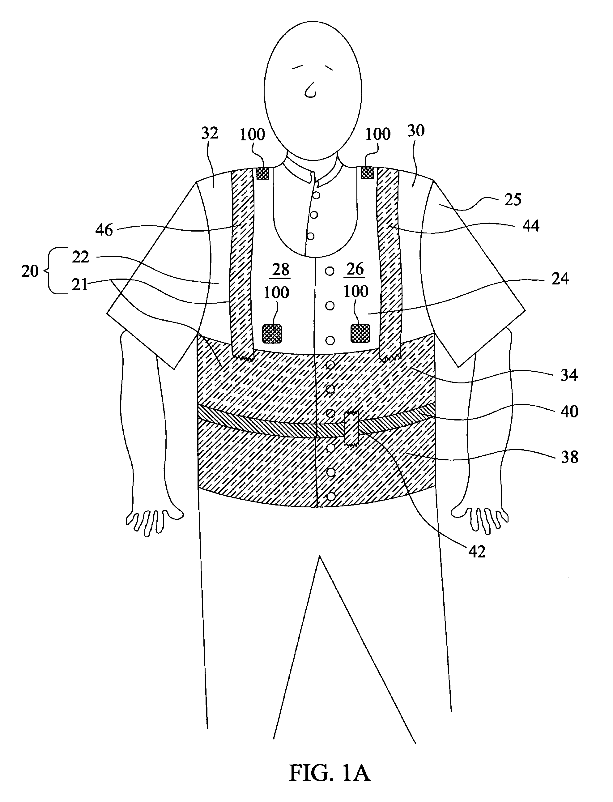
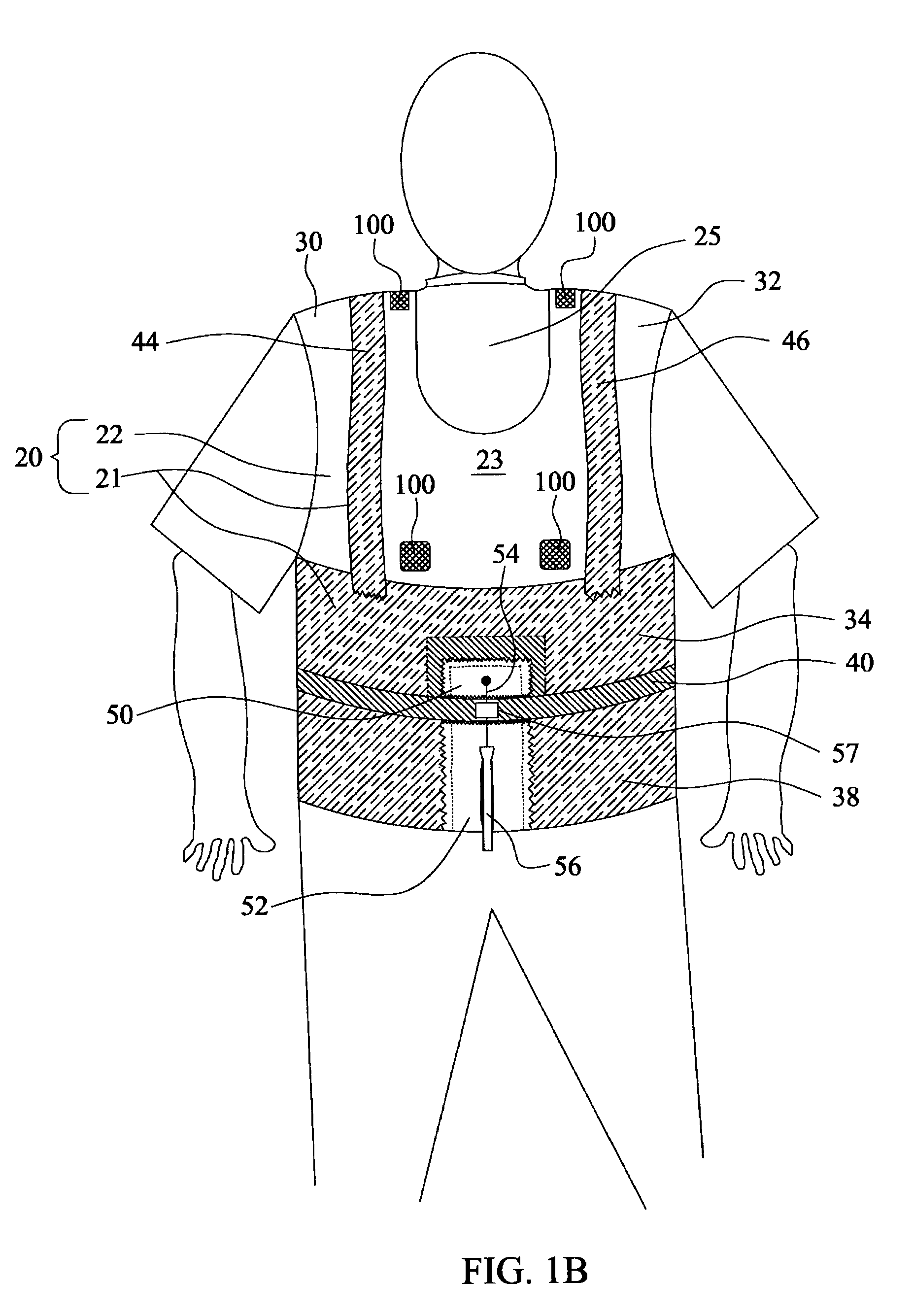
[0021]Referring to FIGS. 1A and 1B, an antenna garment 20 worn by a human wearer 25 is shown that includes a first antenna 21 integrated into a first garment 22. First antenna 21 operates very efficiently over a frequency range of about 30 MHz to about 90 MHz. First antenna 21 is integrated into first garment 22 so that first antenna 21 offers no distinctive visual signature that would identify the person wearing antenna garment 20 as a radio operator. First garment 22 is made of an electrically nonconductive material such as a woven fabric selected from the group that includes cotton, wool, polyester, nylon, Kevlar, rayon, and the like. The electrically conductive material of first garment 22 may also include polyurethane for waterproofing. First garment 22 has an outer layer with an anterior or front section 24 and a dorsal or back region 23. From the perspective of the human wearer 25, front section 24 of first garment 22 includes a left anterior front section 26 and a right ante...


PUM


Abstract

A multi-antenna garment comprising a first and second antenna incorporated into an electrically nonconductive garment, with tubular composites to improve gain and mitigate radiation hazard. The first antenna includes first and second RF elements attached to a first garment so that a gap exists between them, where the RF elements each form a band when the garment is worn by a wearer. The second antenna includes third, fourth, fifth, and sixth RF elements attached to a second garment worn over the first garment. RF feeds are electrically connected to the first, third, and fifth RF elements. Ground feeds are electrically connected to the second, fourth, and sixth RF elements. Insulating material disposed over gaps between the first and second, the third and fourth, and the fifth and sixth RF elements and in pockets in the regions of the RF feeds limits the wearer's exposure to electromagnetic field to acceptable levels.

Description

CROSS REFERENCES TO RELATED APPLICATIONS[0001]This application is a continuation-in-part of U.S. patent application Ser. No. 10 / 263,943, entitled ULTRA-BROADBAND ANTENNA INCORPORATED INTO A GARMENT WITH RADIATION ABSORBER MATERIAL TO MITIGATE RADIATION HAZARD, filed on Oct. 3, 2002 and issued as U.S. Pat. No. 6,788,262 on Sep. 7, 2004, which is a continuation-in-part of U.S. patent application Ser. No. 10 / 061,639, entitled ULTRA-BROADBAND ANTENNA INCORPORATED INTO A GARMENT, filed on Jan. 31, 2002 and issued as U.S. Pat. No. 6,590,540 on Jul. 8, 2003, and which is herein incorporated by reference.BACKGROUND OF THE INVENTION[0002]This invention relates generally to the field of antennas. More specifically, this invention relates to an improved ultra-broadband antenna, comprising of a first and second antenna, which is incorporated into a garment that may be worn around a human torso.[0003]The purpose of the first and second antenna incorporated into a garment is to provide ultra-wide...

Claims


Application Information

Patent Timeline
Patent Type & Authority Patents(United States)
IPC IPC(8): H01Q1/12H01Q1/27H01Q21/30
CPCH01Q1/273H01Q21/30
Inventor ADAMS, RICHARD C.
Owner NAVY SEC OF THE UNITED STATES
Why Eureka
Try Eureka