Method and apparatus for reducing the visibility of streaks in images generated using scanning techniques

a scanning technique and image technology, applied in the field of image forming apparatus, can solve the problems of difficult to implement an analog circuit changing the light emitting quantity at high speed, the speedup of the rotational speed of the polygon mirror and the video clock is in a difficult state, and the degree of freedom of image forming can be increased

Inactive Publication Date: 2005-12-06
FUJIFILM BUSINESS INNOVATION CORP
View PDF13 Cites 17 Cited by
  • Summary
  • Abstract
  • Description
  • Claims
  • Application Information

AI Technical Summary

Benefits of technology

[0034]Since the (m / n)-time exposures are performed per one line, the light intensity of the laser can be largely decreased in one main scanning, and the change in the density, which is generated in the joint of the scanning, can be decreased. Further, since the multiple exposures are performed per one line and the amount of movement in the sub-scanning direction is decreased in each one main scanning period, the period of the streak generation in the image becomes n times, which causes the spatial frequency to increase. Consequently, the visibility of the streak can be decreased. Also, because the determination or control is not performed about the particular elements of the laser array, the complexity of the light intensity controlling circuit can be prevented.
[0036]Since the value of the n lines is set according to the operational mode, the number of exposures (m / n) per one line can be changed, and the degree of freedom of the image formation can be increased. In the case of m=n, the adjacent scanning can be performed.
[0037]For example, as operational modes, there are a monochrome mode forming the monochrome image and a color mode forming the color image. In this case, the value of the n lines in the color mode should be set smaller than that in the monochrome mode. As a result, the number of exposure times per one line is larger in the color mode than in the monochrome mode, so that the high quality image can be obtained. On the other hand, the number of exposure times per one line is lower in the monochrome mode than in the color mode, so that the image forming speed can be increased.
[0039]Substantial evenness of the exposure conditions of each scanning line can suppress the generation of the image streak in such a manner that the emitted element is changed in each scanning to perform the interlaced scanning. Further, since it is not necessary to change the optical system for the case in which the adjacent scanning is performed, the degree of freedom is not decreased for the optical design.
[0041]Since the interlaced scanning is performed in the case of the first operational mode and the adjacent scanning is performed in the case of the second operational mode, the degree of freedom of the image forming can be increased.
[0043]The multiple scannings are performed per one line in the case of the first operational mode and the interlaced scanning is performed in the case of the second operational mode, so that the degree of freedom of the image forming can be increased.

Problems solved by technology

In the image forming apparatus such as the copying machine or the laser printer, in which the laser beam scans a photosensitive body or the like to form the image, while high-speed and high-resolution proceed, the speedups of a rotational speed of a polygon mirror and a video clock are in a difficult state.
In the photosensitive body of an electrophotographic apparatus and the like, when the exposure is performed by the laser and the like as a light source, it is reported that charge / antistatic characteristics of the photosensitive body is varied by difference in exposure form, which is caused by the reciprocity law failure.
According to the method, in the case of the image in which only one of the m beam in the Nth time and the first beam in the (N+1)-th time, because the reciprocity law failure is not generated, there is generated the problem that the image density is decreased corresponding to the decreased light intensity.
However, in the exposure apparatus having the multi beam scanning causing such a problem, it is difficult to implement an analogue circuit changing the light emitting quantity at high speed during referring to the image data for high speed and high resolution recording.
Further, there is the problem that a fast light intensity modulating circuit is also required in order to change the light intensity of the laser in each pixel according to the printing image.
There is also the problem that it is necessary to change laser output largely, and the variable range of the laser output is large in order to decrease the image streak by adjusting the light intensity of the one laser (first or mth laser) or the two lasers (first and mth lasers) of the joint.
In JP-A No. 4-149523 (Japanese Patent No. 2628934), the speed of a galvanometer mirror is changed in order to change the intervals of the joint, however, according to the method, there is the problem that the image in the sub-scanning direction is expanded or contracted.
However, in the image forming apparatus described in JP-A No. 5-42716, the purpose of the apparatus is to solve shortage of the light intensity of the element, and there is the problem unevenness of the density is generated in the joint of the image when the number of beams is increased.

Method used


Image

  • Method and apparatus for reducing the visibility of streaks in images generated using scanning techniques
  • Method and apparatus for reducing the visibility of streaks in images generated using scanning techniques
  • Method and apparatus for reducing the visibility of streaks in images generated using scanning techniques

Examples


first embodiment

(First Embodiment)

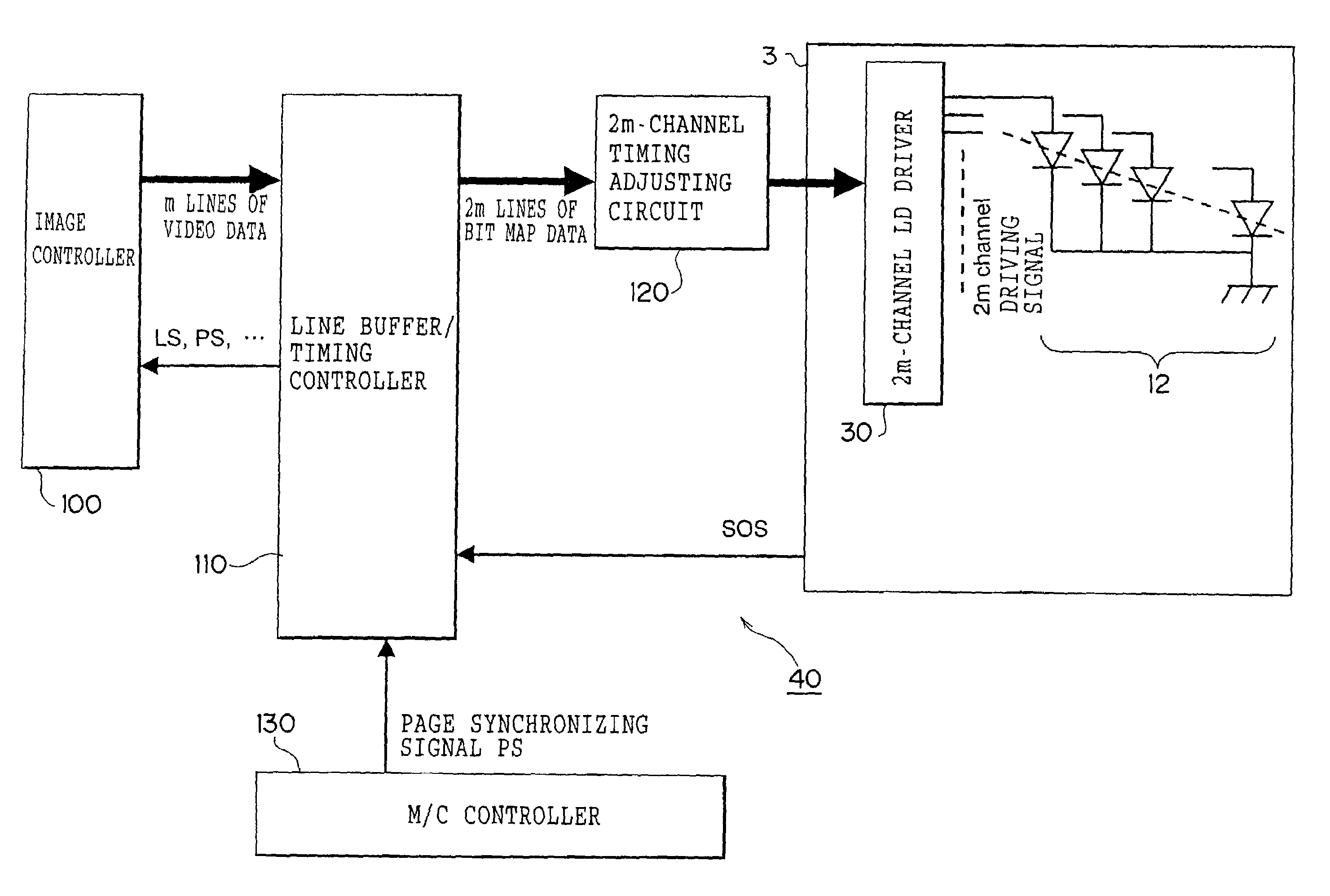
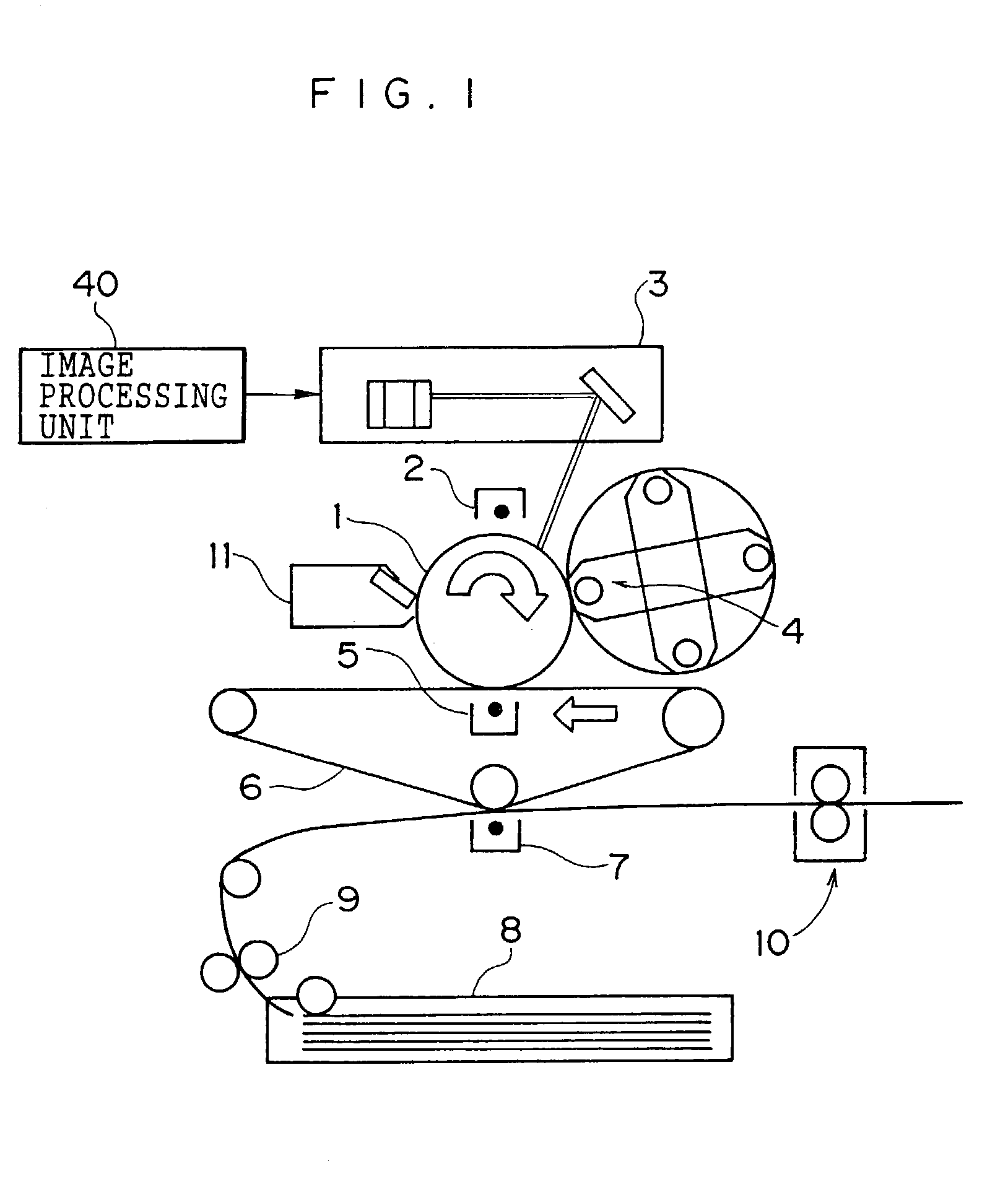
[0063]FIG. 1 shows a configuration of a color image forming apparatus according to a first embodiment, which utilizes an electrophotographic process.

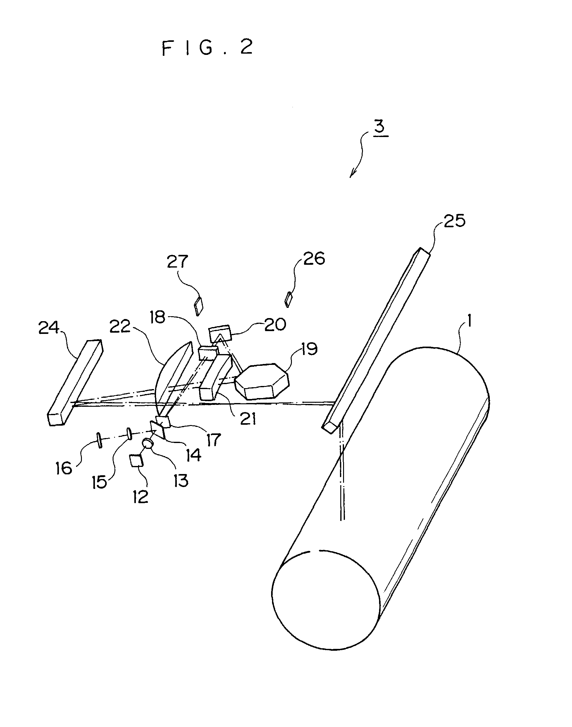
[0064]The color image forming apparatus according to the embodiment includes a photosensitive body 1 rotating in an arrow direction, a charging device 2 charging a surface of the photosensitive body 1, an exposure device 3 exposing the surface of the photosensitive body 1, a developing device 4 performing the development with toner, a primary transfer device 5 performing the primary transfer of a toner image, an intermediate transfer belt 6 to which the toner image is transferred by the primary transfer device 5, a secondary transfer device 7 transferring the toner image of the intermediate transfer belt 6 to the paper, a paper tray 8 storing the paper, a paper carrying roller 9 carrying the paper in a given direction, a fixing device 10 melting and fixing the toner image, a cleaning device 11 removing the residual ton...

second embodiment

(Second Embodiment)

[0109]A second embodiment of the invention will be described. The same reference numerals are used for the same part as that of the first embodiment, and the overlapped description is omitted.

[0110]Though the color image forming apparatus according to the embodiment is formed in almost the same way as the first embodiment, an interlaced scanning is utilized as the laser scanning method.

[0111]FIG. 9 shows a combination of m and n, in which the interlaced scanning can be performed, when the number of beams is set to m and an interlaced period is set to n. According to FIG. 9, in order to perform the interlaced scanning, it is required that m and n are prime natural numbers each other (see JP-A No. 5-53068).

[0112]FIG. 10 shows the scanning lines when the interlaced scanning has been performed in the case that the number of laser elements of the vertical-cavity surface-emitting laser array is 4.

[0113]According to FIGS. 9 and 10, the interlaced period n must be not low...

third embodiment

(Third Embodiment)

[0132]A third embodiment of the invention will be described.

[0133]The color image forming apparatus can output the color image and the monochrome (B / W) image, and have a plurality of image quality modes. As concerns the image quality mode, for example, there is the color mode in which the high quality image is required rather than the speed, the monochrome mode in which productivity (high speed) is required rather than the image quality, or the like.

[0134]Although, the image forming apparatus adopting the double scanning method shown in the first embodiment and the image forming apparatus adopting the interlaced scanning method shown in the second embodiment can form the high quality image, since the shift in the sub-scanning direction is half of the adjacent scanning, the double scanning method and the interlaced scanning method do not reach the adjacent scanning method for the productivity.

[0135]Accordingly, the image forming apparatus according to the third embo...


PUM


Abstract

A plurality of beams scan the photosensitive body or the like so that a high quality image whose streak is not recognized by a human eye can be formed. 2m lines are formed simultaneously in Nth time, (N+1)-th time, and (N+2)-th time scannings respectively. At this point, the m lines are fed in a sub-scanning direction at each termination of one-time scanning, and the next scanning is performed. Accordingly, a region which is exposed twice between the scannings is generated at an m-line period.

Description

BACKGROUND OF THE INVENTION[0001]1. Field of the Invention[0002]The present invention relates to an image forming apparatus, particularly relates to an image forming apparatus such as a copying machine or a laser printer, in which a plurality of laser beams are scanned to form an image.[0003]2. Description of the Related Art[0004]In the image forming apparatus such as the copying machine or the laser printer, in which the laser beam scans a photosensitive body or the like to form the image, while high-speed and high-resolution proceed, the speedups of a rotational speed of a polygon mirror and a video clock are in a difficult state. Therefore, the speedup and the high-resolution are being attempted by increasing the number of light sources.[0005]The image forming apparatus, in which a plurality of beams scans and exposes a scanned body such as a photosensitive body, have been applied to the patent. With reference to a scanning method, an adjacent scanning has been proposed to form a...

Claims


Application Information

Patent Timeline
Patent Type & Authority Patents(United States)
IPC IPC(8): B41J2/44B41J2/455B41J2/47G02B26/10H04N1/113
CPCB41J2/45B41J2/473
Inventor TAKAMATSU, MASAHIROISHII, AKIRA
Owner FUJIFILM BUSINESS INNOVATION CORP
Why Eureka
Try Eureka