
Method and apparatus for signal transmission and reception

a signal transmission and reception technology, applied in the field of signal transmission and reception systems, can solve the problem that prior art modems employing modulation schemes such as qam cannot employ non-linear amplification, and achieve the effects of reducing bandwidth, reducing cost and complexity, and being easy to implemen

Inactive Publication Date: 2005-12-06
MILLER WILLIAM J
View PDF36 Cites 13 Cited by
  • Summary
  • Abstract
  • Description
  • Claims
  • Application Information

AI Technical Summary

Benefits of technology

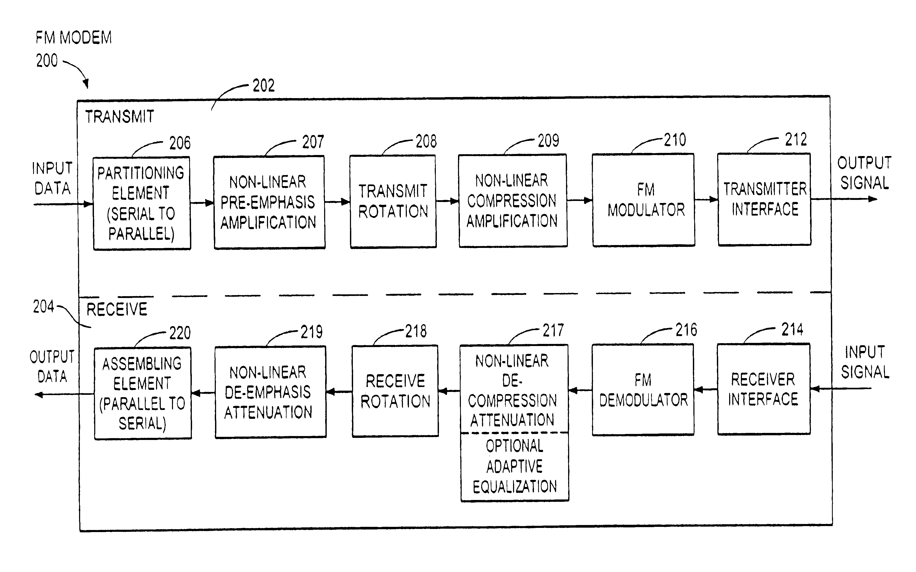
[0013]The polyphase filtration of these methods and this modem enables FM modulation of the transmitted symbols since only a real component of the original symbols is generated. FM, whether achieved using frequency modulation or phase modulation of the input signal, provides enhanced immunity to non-Guassian noise, provides high bandwidth efficiency, utilizes non-coherent IF and thus requires no carrier recovery, is of lower cost than conventional modems in part due to the absence of A / D converters, provides low co-interference due to the FM capture effect, and is compatible with analog signals, owing to the use of commuting operators. More power efficient, but potentially less linear amplifiers such as Class B and Class C can be employed since zero crossings are used to determine data content; carrier recovery is not required. Prior art modems employing modulation schemes such as QAM cannot employ such non-linear amplification. Further, satellite modems employing the presently disclosed method and modem save on Travelling Wave Tube (TWT) backoff power and thus are more energy efficient since intermodulation is not a problem, while personal computers achieve higher data rates without sacrificing bit error rate.
[0018]FM double-side band is employed in systems requiring minimal cost and complexity. FM single-side band is easily implemented in systems in which the bandwidth reduction is desired. AM modulation of a carrier is also implemented in a further embodiment.

Problems solved by technology

Prior art modems employing modulation schemes such as QAM cannot employ such non-linear amplification.

Method used


Image

  • Method and apparatus for signal transmission and reception
  • Method and apparatus for signal transmission and reception
  • Method and apparatus for signal transmission and reception

Examples


Embodiment Construction

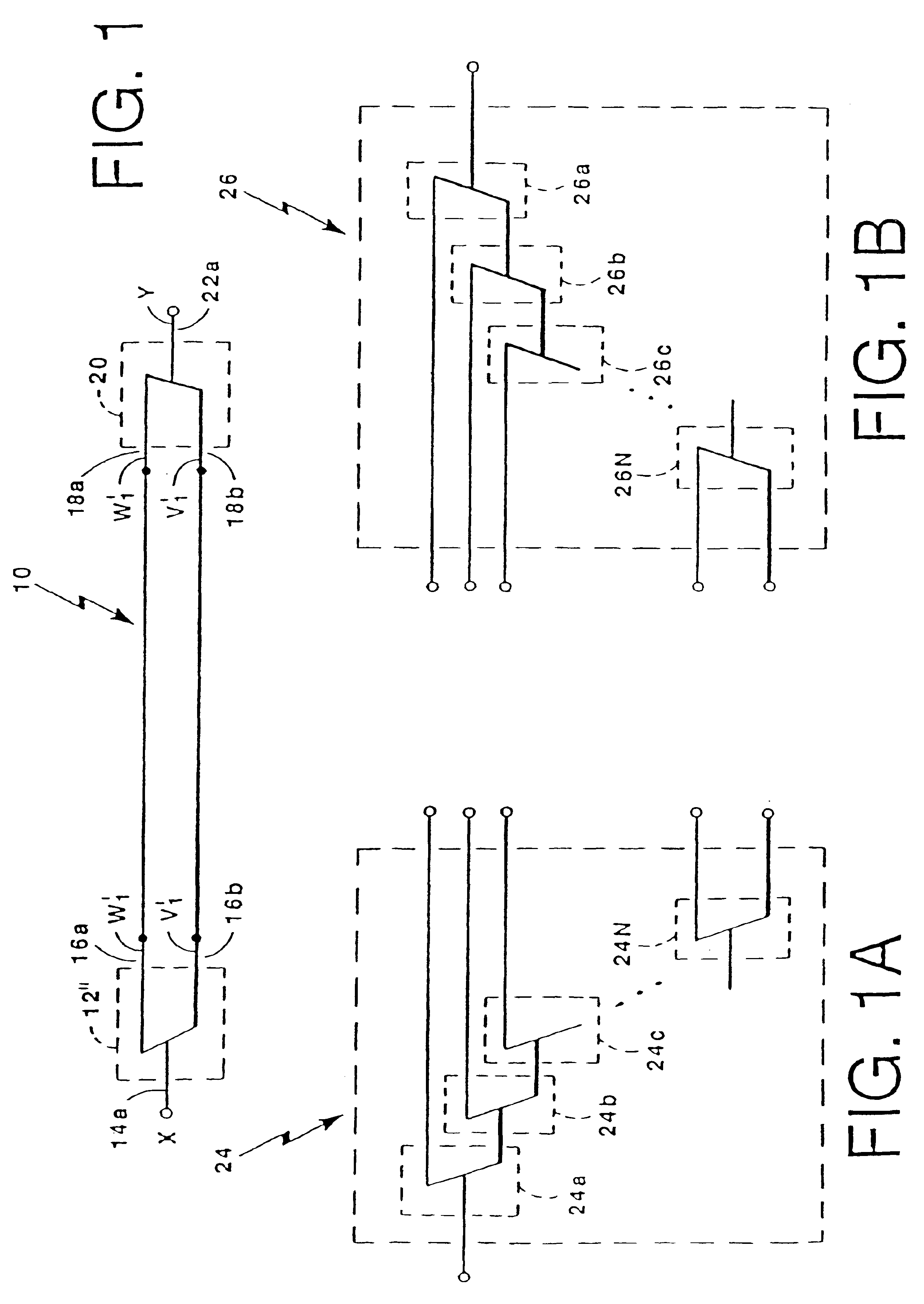
[0040]Referring now to FIG. 1 a signal decomposition-recomposition system 10 includes an analyzer 12 having an input port 14a and a pair of output ports 16a, 16b. Each of the output ports 16a, 16b are coupled to a corresponding pair of input ports 18a, 18b of a synthesizer 20.

[0041]An analog input signal X fed to the analyzer input port 14a is decomposed into a pair of signals W′ and V′ each of which is fed to a corresponding one of the output ports 16a, 16b. Similarly, a pair of input signals W′, V′ fed to the synthesizer input ports 18a, 18b are reconstructed in to an output signal Y at a synthesizer output port 22a. The decomposition and reconstruction processes performed by the analyzer 12 and the synthesizer 20 as well as the signals V′ and W′ will be described further hereinbelow. Suffice it here to say that the input signal X is decomposed into the signals V′ and W′ such that the signals V′ and W′ may later be combined to exactly reconstruct the input signal X.

[0042]It should...


PUM


Abstract

A method for communicating serial input data over a transmission link. Serial input data is partitioned into parallel data elements and is coded prior to rotation by an invertible linear mapping. Resulting frames of parallel sign elements are transmitted over the link. After receipt from the link, the signal is assembled into frames of parallel signal elements which are de-rotated by an inverse linear mapping, then decoded. Thresholding the result of the inverse mapping recovers the parallel data elements, which are then re-assembled into serial output data. The linear mapping employs: 1) commuting rotation matrices for convolutionally rotating data vectors into signal vectors and vice-versa; 2) filter bank polyphase rotation matrices; or 3) computationally efficient multi-rate wavelet filter banks. Coefficients of the rotation matrix of the receiver are adaptively equalized to correct for transmission path distortion.

Description

RELATED APPLICATIONS[0001]This Application is a CON of Ser. No. 10 / 379,870 filed in Mar. 05, 2003 ABN which is a CON of Ser. No. 09 / 894,168 filed on Jun. 27, 2001 U.S. Pat. No. 6,532,256 which is a CON of Ser. No. 09 / 450,085 filed on Nov. 29, 1999 U.S. Pat. No. 6,263,017 which is a CON of Ser. No. 08 / 634,179 filed on Apr. 18, 1996 U.S. Pat. No. 5,995,539 which is a CIP of Ser. No. 08 / 342,259, filed Nov. 18, 1994 ABN which is a CON Of Ser. No. 08 / 033,518 filed on Mar. 17, 1993 U.S. Pat. No. 5,367,516.FIELD OF THE INVENTION[0002]This invention relates to signal transmitting and receiving systems and more particularly to modems employing polyphase filtering techniques.BACKGROUND OF THE INVENTION[0003]As is known in the art, a modulator-demodulator (modem) is an electronic device that modulates transmitted signals and demodulates received signals. The modem generally provides an interface between digital devices and an analog communications system to thus make possible analog transmissi...

Claims


Application Information

Patent Timeline
Patent Type & Authority Patents(United States)
IPC IPC(8): H04K1/02H04L25/03
CPCH04K1/02H04L25/03343H04L69/40
Inventor MILLER, WILLIAM J.
Owner MILLER WILLIAM J
Learn More