Gas offloading system

a gas offloading and gas technology, applied in the direction of container discharge methods, special purpose vessels, packaged goods types, etc., can solve the problems of high fixed platform cost, difficult to moor a tanker to the platform, and high cost of fixed platform, so as to achieve the effect of easy passing

Active Publication Date: 2005-12-13
SINGLE BUOY MOORINGS INC
View PDF7 Cites 35 Cited by
  • Summary
  • Abstract
  • Description
  • Claims
  • Application Information

AI Technical Summary

Benefits of technology

[0004]In accordance with one embodiment of the present invention, a relatively low-cost system is provided for offloading cold hydrocarbons, and especially LNG (liquified natural gas), and transporting the gas to an onshore gas distribution station. The system includes a floating structure such as a barge at the sea surface that is moored so it weathervanes. A tanker carrying LNG attaches itself to the floating structure so they weathervane together. A regas unit which heats the LNG, usually by transferring heat from sea water, transforms the LNG into gas that can be more easily passed through moderate cost hoses or pipes and eventually to the onshore distribution station.
[0006]The regas unit and pumps for pressurizing gas, are preferably electrically energized for safety and convenience. Electric power on the order of 60 megawatts may be required. Such electrical energy can be obtained from a power generator apparatus on the floating structure that uses gas from the tanker for fuel. The regas unit may require electric power only part of the time, such as one day per week when LNG is being offloaded and regassed. The rest of the time (e.g. several days per week) electric power from the power generator apparatus is passed through a seafloor electric power line to an onshore electric distribution facility. The generation of electric power at the floating structure is economical because the gas fuel is already available and because a large amount of expensive land is not required to isolate the power generation apparatus from onshore homes and businesses for safety.

Problems solved by technology

The cost of a fixed platform is high even at moderate depths, and at increasing depths (e.g. over 50 meters) the costs of fixed platforms increase dramatically.
In addition, if the platform lies in an open sea it is difficult to moor a tanker to the platform because the tanker shifts position and heading with changing winds, waves and currents.

Method used


Image

  • Gas offloading system
  • Gas offloading system
  • Gas offloading system

Examples


Embodiment Construction

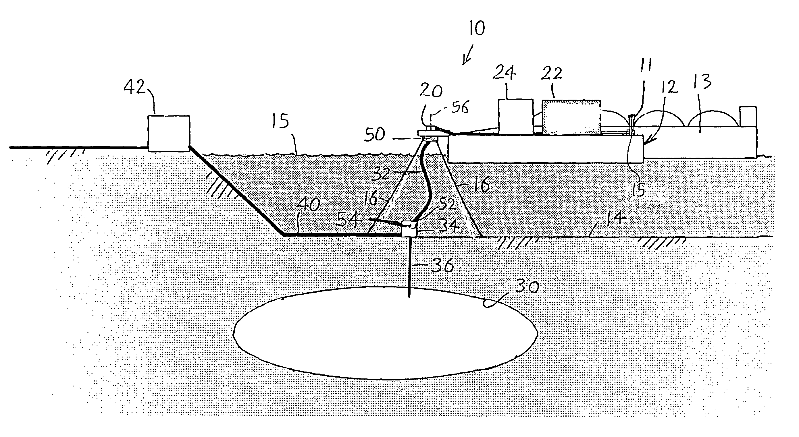
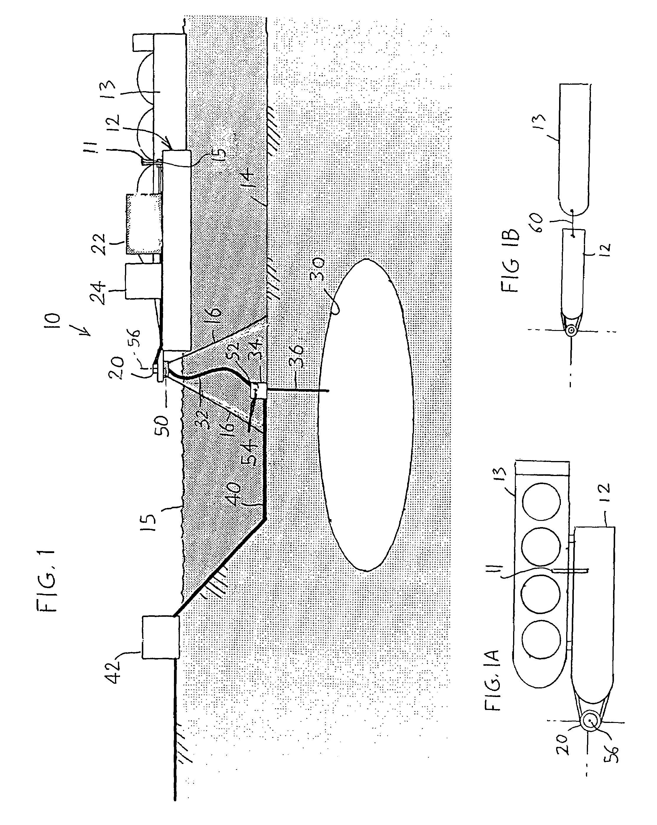
[0019]FIG. 1 illustrates an offloading and transfer station 10 that includes a weathervaning floating structure in the form of a single barge 12 (there could be more than one barge) that floats at the sea surface 15. The barge receives LNG through a coupling 15 and a loading arm 11 extending from midship of a tanker 13. The barge is moored to the seafloor 14 by chains 16 extending from a turret 20 mounted at the bow of the barge. The illustrated chains extend in catenary curves to the seafloor and along the seafloor to anchors. Preferably, the tanker is moored to the barge and they weathervane together. This allows the barge and tanker to move in unison and therefore remain close together in an open sea. A regas unit 22 (for heating LNG to produce gas) and an injection unit 24 for pumping the LNG or gas to a high pressure, are both located on the barge, and are used for injection of gas into an underground cavern 30 that lies under the sea. The regas unit usually transfers heat from...


PUM

PropertyMeasurementUnit
depthsaaaaaaaaaa
temperatureaaaaaaaaaa
currentaaaaaaaaaa

Abstract

A system is described for offloading LNG (liquified natural gas) from a tanker for eventual delivery to an onshore gas distribution station. The system includes a floating structure that floats at the sea surface and that is connected to the tanker so they weathervane together. The floating structure carries a regas unit that heats the LNG to produce gas, and delivers the gas through a riser to an underground cavern that stores the gas. Gas from the cavern is delivered through a seafloor pipeline to an onshore gas distribution station. The regas unit includes water pumps and other equipment that is powered by electricity. The electricity can be obtained from an electric generator on the floating structure, with surplus electricity delivered through a sea floor electric power line that extends along the sea floor to an onshore electricity distribution facility. The electricity can instead be obtained by delivery from an onshore facility though a sea floor electric power line that extends up to the floating structure and to the regas unit.

Description

CROSS REFERENCE[0001]Applicant claims priority from U.S. Provisional application Ser. No. 60 / 504,449 filed 19 Sep. 2003 and Ser. No. 60 / 515,767 filed 30 Oct. 2003.BACKGROUND OF THE INVENTION[0002]Hydrocarbons that are in a gaseous state at atmospheric pressure and room temperature (e.g. 20° C.), are often transported as cold hydrocarbons, as by ship in liquid form such as LNG (liquified natural gas), at atmospheric pressure and −160° C. Another form of cold gaseous hydrocarbons that are ship-transported are hydrates (gas entrapped in ice). At the ship's destination, the LNG (or other gas) may be heated and flowed to an onshore distribution facility. Proposed prior art offloading stations have included a fixed platform extending up from the sea floor to a height above the sea surface and with a regas unit on the platform for heating the LNG. Because of fire dangers in dealing with LNG, rigid platforms, which minimize flexing joints, have previously been proposed for offloading LNG fr...

Claims


Application Information

Patent Timeline
Patent Type & Authority Patents(United States)
IPC IPC(8): B65B1/04F17C9/00F17C9/02
CPCB63B21/50B63B27/24F17C9/00F17C9/02F17C2221/033F17C2223/0161F17C2223/033F17C2225/0123F17C2225/0161F17C2225/035F17C2225/036F17C2227/0157F17C2227/0318F17C2227/0393F17C2265/05F17C2270/0105F17C2270/0113F17C2270/0123F17C2270/0126F17C2270/0136F17C2270/0142F17C2270/0149F17C2270/0155F17C2270/016F17C2270/0163
Inventor POLLACK, JACKWILLE, HEIN
Owner SINGLE BUOY MOORINGS INC
Why Eureka
Try Eureka