Braking device for a dual bearing reel

a technology of braking device and reel, which is applied in the direction of reels, electrodynamic brake systems, vehicle components, etc., can solve the problems of easy deterioration of lead wire insulation, easy assembly of braking device, and generation of braking force, so as to reduce poor insulation and facilitate assembly. braking device

Active Publication Date: 2005-12-13
SHIMANO INC
View PDF4 Cites 53 Cited by
  • Summary
  • Abstract
  • Description
  • Claims
  • Application Information

AI Technical Summary

Benefits of technology

[0010]An object of the present invention is to reduce the poor insulation be...

Problems solved by technology

However, mechanical spool braking devices only generate braking force that is in proportion to the rotational speed of the rotor or the square of the rotational speed, and thus generate braking force even at times when it is not needed.
Thus if ...

Method used


Image

  • Braking device for a dual bearing reel
  • Braking device for a dual bearing reel
  • Braking device for a dual bearing reel

Examples


first embodiment

[0056

[0057]Configuration of the Reel

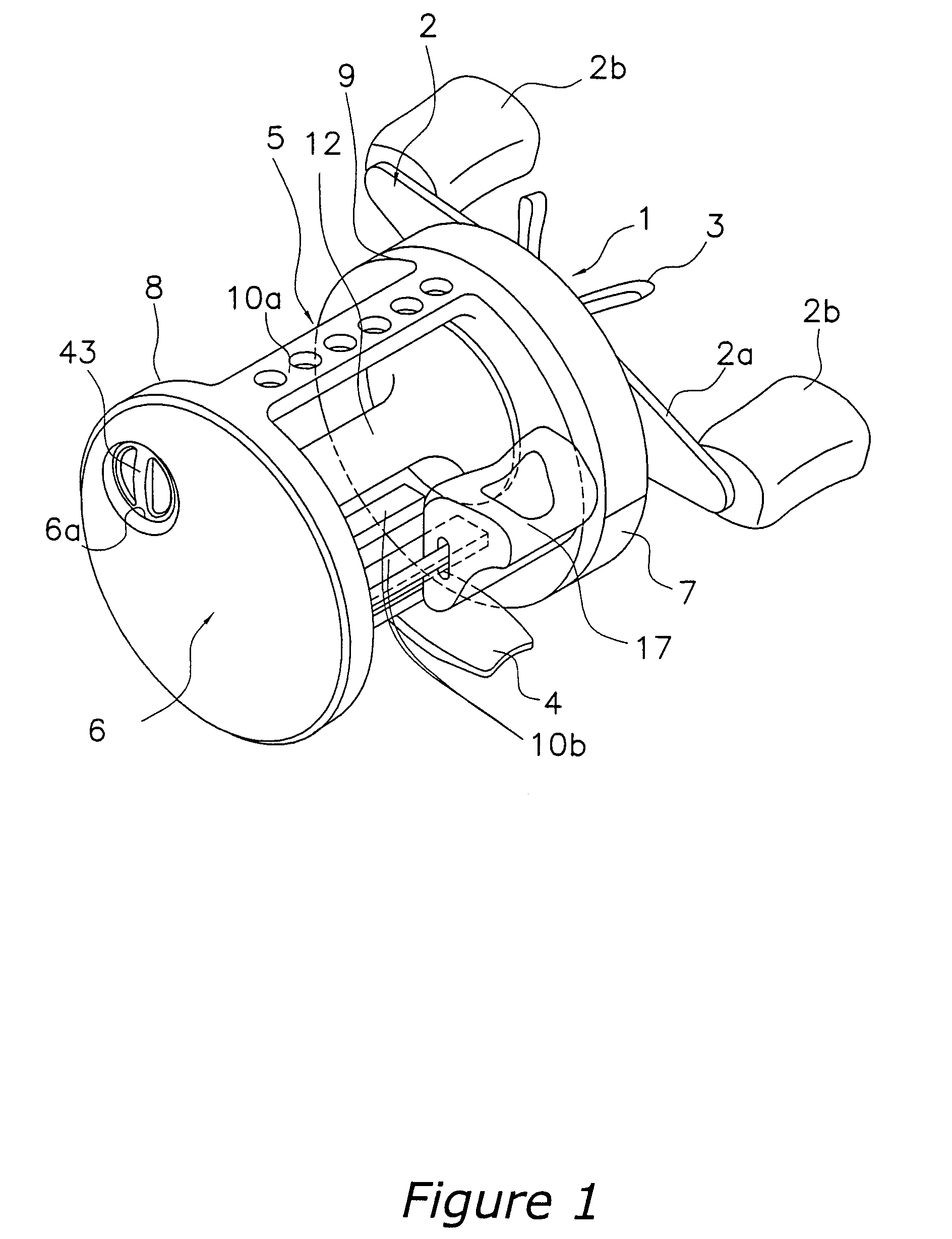
[0058]In FIG. 1 and FIG. 2, a dual bearing reel according to one embodiment of the present invention is a round dual bearing reel for bait casting. This reel includes a reel unit 1, a handle 2 for rotating the spool that is disposed on the side of the reel unit 1, and a star drag 3 for adjusting drag that is disposed on the same side of the reel unit 1 as the handle 2.

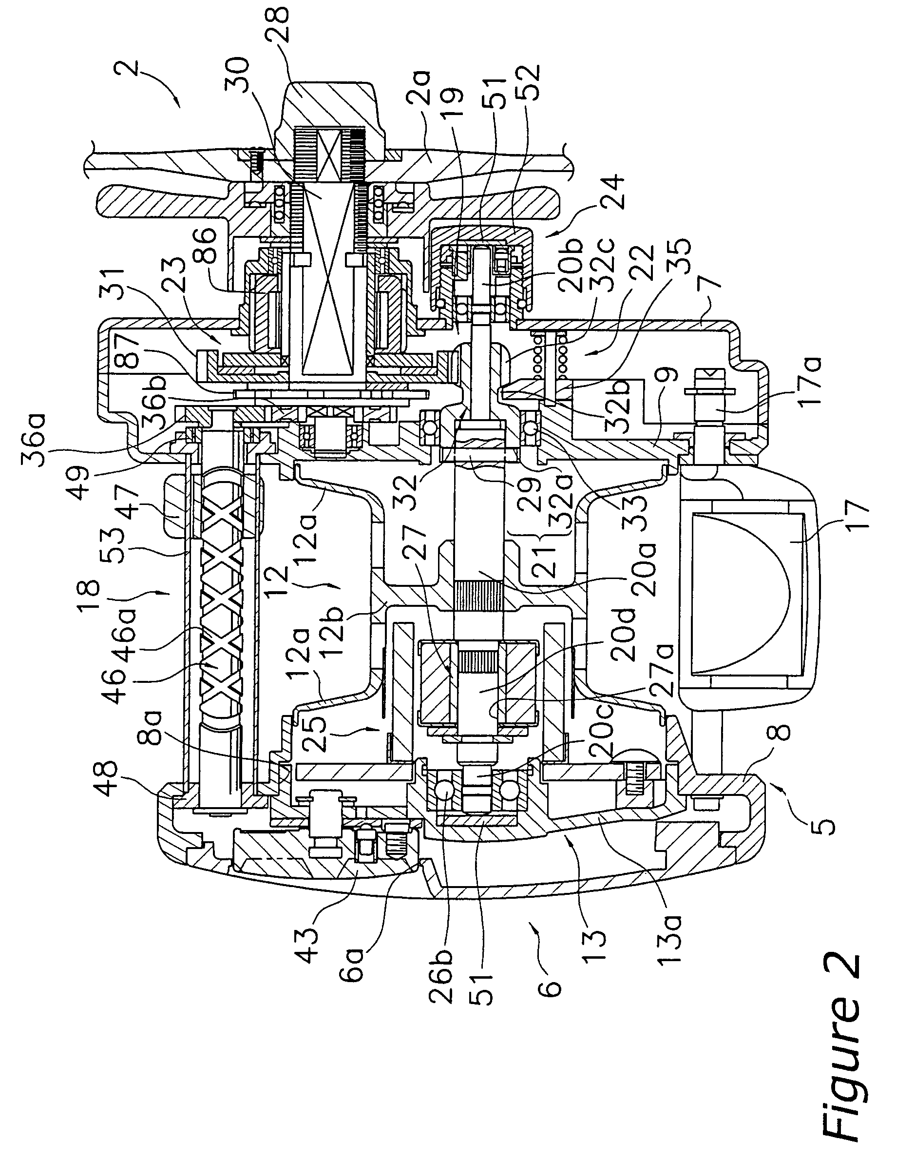
[0059]The handle 2 is of the double-handle type and has a plate-shaped arm portion 2a and knobs 2b that are rotatively mounted to both ends of the arm portion 2a. As shown in FIG. 2, the arm portion 2a is non-rotatively mounted to the end of a handle shaft 30, and is fastened to the handle shaft 30 by a nut 28.

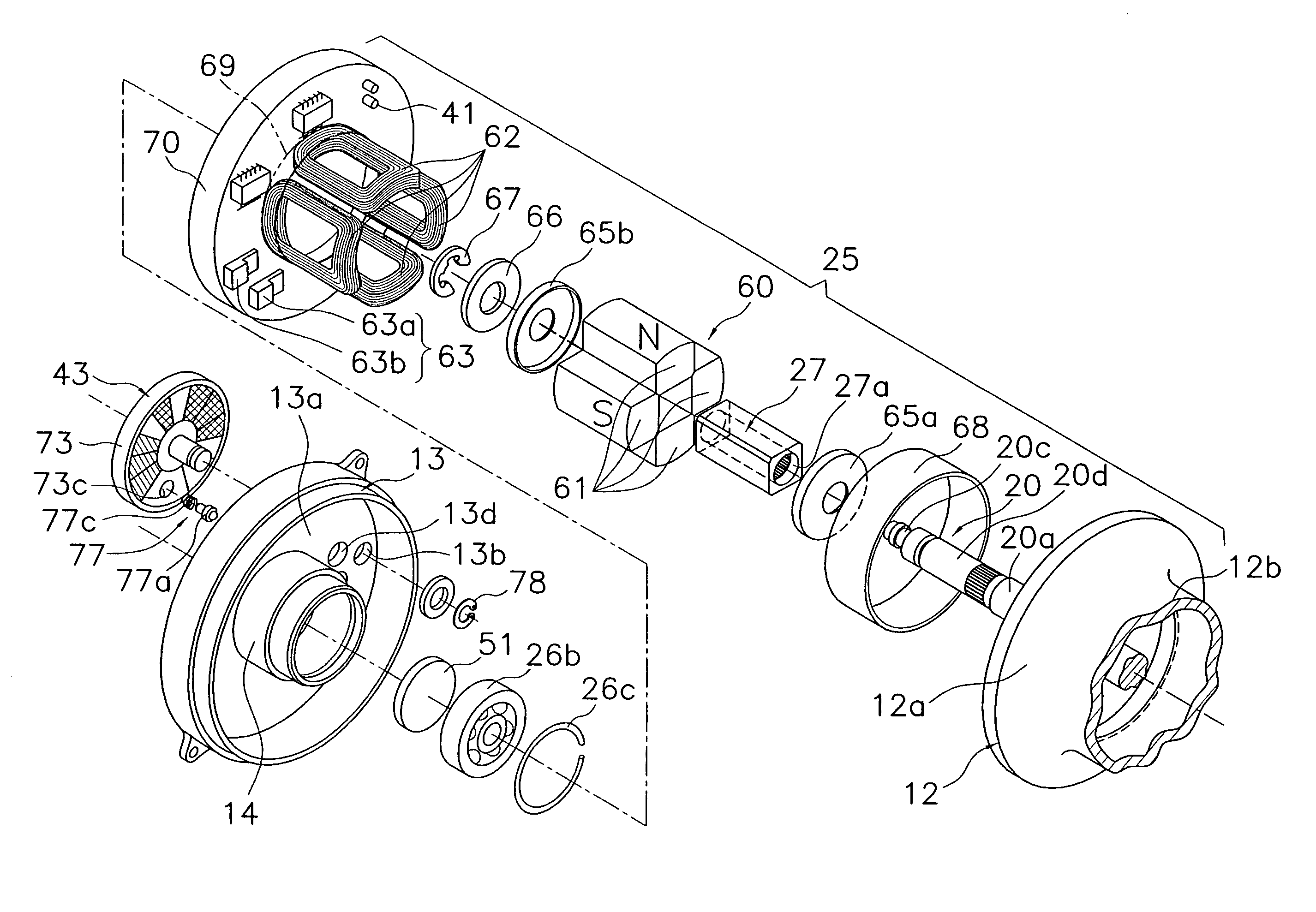
[0060]The reel unit 1 is, for example, made of a metal such as an aluminum alloy or a magnesium alloy, and includes a frame 5, and a first side cover 6 and a second side cover 7 that are mounted to both sides of the frame 5. A spool 12 for winding fishing line is rotatively mou...

second embodiment

[0124

[0125]In the first embodiment, the insulating coating film 90 is formed on the whole surface of the circuit board 70. However, it is possible to form insulating coating selectively. The description below abbreviates the explanation of constitution and operation that are identical or equal with those of the first embodiment.

[0126]As shown in FIGS. 12–14A, 14B, in the second embodiment, the switch element 63 includes, for example, two parallel connected FET (field effect transistors) 63a that can switch on and off at a high speed. The serially connected coils 62 are connected to each drain terminal of the FET 63a. As shown in FIG. 14B, the switch element 63 is mounted to the rear surface of the circuit board 70 (the surface on the opposite side of the front surface facing the flange portions 12a).

[0127]The rotational speed sensor 41 employs, for example, a reflection type electro-optical sensor 44 that includes a light 44a and a receptor 44b, and is disposed on the front surface ...

third embodiment

[0137

[0138]In a third embodiment, explanation is given concerning when insulating coating film is formed with hot melt molding method. Furthermore, in the following discussion of the third embodiment, explanation of constitution and operation that are identical or equal with those of the first and second embodiments will be omitted.

[0139]As shown in FIGS. 16 and 17A, 17B, in the third embodiment, the switch element 63 includes, for example, two parallel connected FET (field effect transistors) 63a that can switch on and off at a high speed. The serially connected coils 62 are connected to each drain terminal of the FET 63a. As shown in FIG. 17B, the switch element 63 is mounted to the rear surface of the circuit board 70 (the surface on the opposite side of the front surface facing the flange portions 12a).

[0140]The circuit board 70 is a washer-shaped and ring-shaped substrate having a circular opening in the center thereof, and is disposed on the outer peripheral side of the bearin...


PUM


Abstract

A braking device for a dual bearing reel includes a spool braking unit and a spool control unit. The spool braking unit includes a rotor element that rotates in association with the spool and includes a plurality of magnets sequentially arranged in the rotational direction, a plurality of serially connected coils that are disposed around a periphery of the rotor element in a circumferential direction, and a switch element that is connected to both ends of the plurality of the serially connected plurality of coils. The spool control unit electrically controls the spool braking unit, and includes a circuit board on which the plurality of coils are installed and which is mounted on the reel unit, and a controller that is mounted on the circuit board. This way, insulation on the coil and on a circuit board and secured. It is also easier to assemble a braking device.

Description

BACKGROUND OF THE INVENTION[0001]This application claims priority to Japanese Patent Applications Nos. 2003-00648, 2003-00649, 2003-154602, 2003-154604. The entire disclosure of Japanese Patent Nos. 2003-00648, 2003-00649, 2003-154602, 2003-154604 is hereby incorporated herein by reference.[0002]1. Field of the Invention[0003]The present invention relates to a braking device. More particularly the present invention relates to a braking device for a dual bearing reel that brakes a spool rotatively mounted to a reel unit.[0004]2. Background Information[0005]A braking device is provided in dual bearing reels in order to brake the spool, and in particular is provided in bait casting reels in which tackle or the like is mounted to the end of a fishing line and cast out in order to prevent a backlash during casting. Many of these conventional braking devices are of the mechanical type, which use centrifugal force or magnetic force. However, mechanical spool braking devices only generate b...

Claims


Application Information

Patent Timeline
IPC IPC(8): A01K89/0155A01K89/033
CPCA01K89/01555A01K89/033
Inventor IKUTA, TAKESHIKAWASAKI, KEN'ICHIHIRAIZUMI, KAZUKI
Owner SHIMANO INC
Why Eureka
Try Eureka