Analyte pre-concentrator for gas chromatography

a gas chromatography and analyte technology, applied in the field of preconcentration analytes, can solve the problems of increasing the concentration of other materials, affecting the sensitivity of the system, and requiring frequent replacement, and repeated use of anhydrous substances is likely to be limited

Inactive Publication Date: 2005-12-13
PERKINELMER HEALTH SCIENCES INC
View PDF40 Cites 35 Cited by
  • Summary
  • Abstract
  • Description
  • Claims
  • Application Information

AI Technical Summary

Benefits of technology

[0010]Accordingly, an object of the present invention is to provide an analyte pre-concentrator for gas chromatography that permits temperature increases without detrimentally affecting the sensitivity of the chromatographic system.
[0012]It is yet another object of the present invention to provide an analyte pre-concentrator for gas chromatography that provides a moisture trap resulting in little or no dead volume between the trap and a chromatographic column, thereby decreasing excessive peak broadening.
[0013]It is still another object of the present invention to provide an analyte pre-concentrator for gas chromatography that provides a moisture trap without the addition of a separate device, thereby decreasing manufacturing and maintenance costs.

Problems solved by technology

A disadvantage of such devices, however, is that such temperature increases may also increase the concentration of other material that detrimentally affects the sensitivity of the system, such as water.
However, because the anhydrous substance absorbs the water, rather than adsorbing the analyte and allowing the water to be purged from the system, repeated use of the anhydrous substance is likely to be limited and require frequent replacement.
However, a disadvantage of this arrangement is the dead volume that exists between the adsorbent bed and the chromatographic column, which is undesirable because, at typical column flow rates, excessive peak broadening results.
However, rather than optimizing the utility of the adsorbent trap itself as a means for analyte pre-concentration and moisture elimination, these assemblies each require a separate device in addition to the trap, which not only creates additional manufacture and maintenance costs, but also does not solve the aforementioned problem of excessive volume between the adsorbent bed and the chromatographic column.
However, the use of such devices presently known in the art, including chromatographic injectors, for headspace applications results in the same disadvantages previously mentioned for introducing samples into chromatographic columns generally.

Method used


Image

  • Analyte pre-concentrator for gas chromatography
  • Analyte pre-concentrator for gas chromatography
  • Analyte pre-concentrator for gas chromatography

Examples


Embodiment Construction

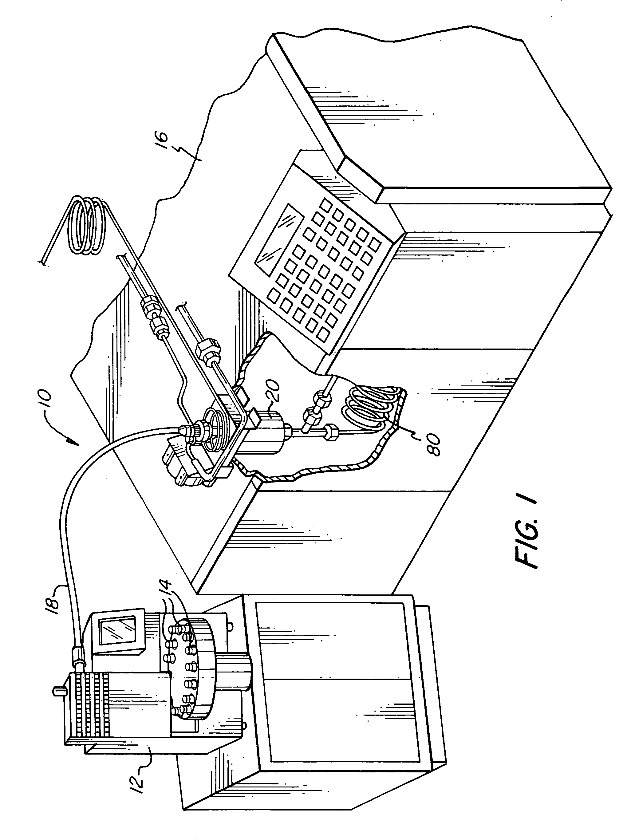
[0032]The basic components of one embodiment of a gas chromatographic sampling system 10 in accordance with the invention are illustrated in FIG. 1. As used in this description, the terms “top,”“bottom,”“upper,” and “lower” refer to the objects referenced when in the orientation illustrated in the drawings, which orientation is not necessary for achieving the objects of the invention.

[0033]In the embodiment depicted in FIG. 1, a headspace sampler 12 holds a plurality of vials 14 that contain the sample to be analyzed. The headspace sampler 12 is connected to a gas chromatograph 16 via a transfer line 18. The basic components of the gas chromatograph are an injector 20, a chromatographic column 80, and a detector (not shown).

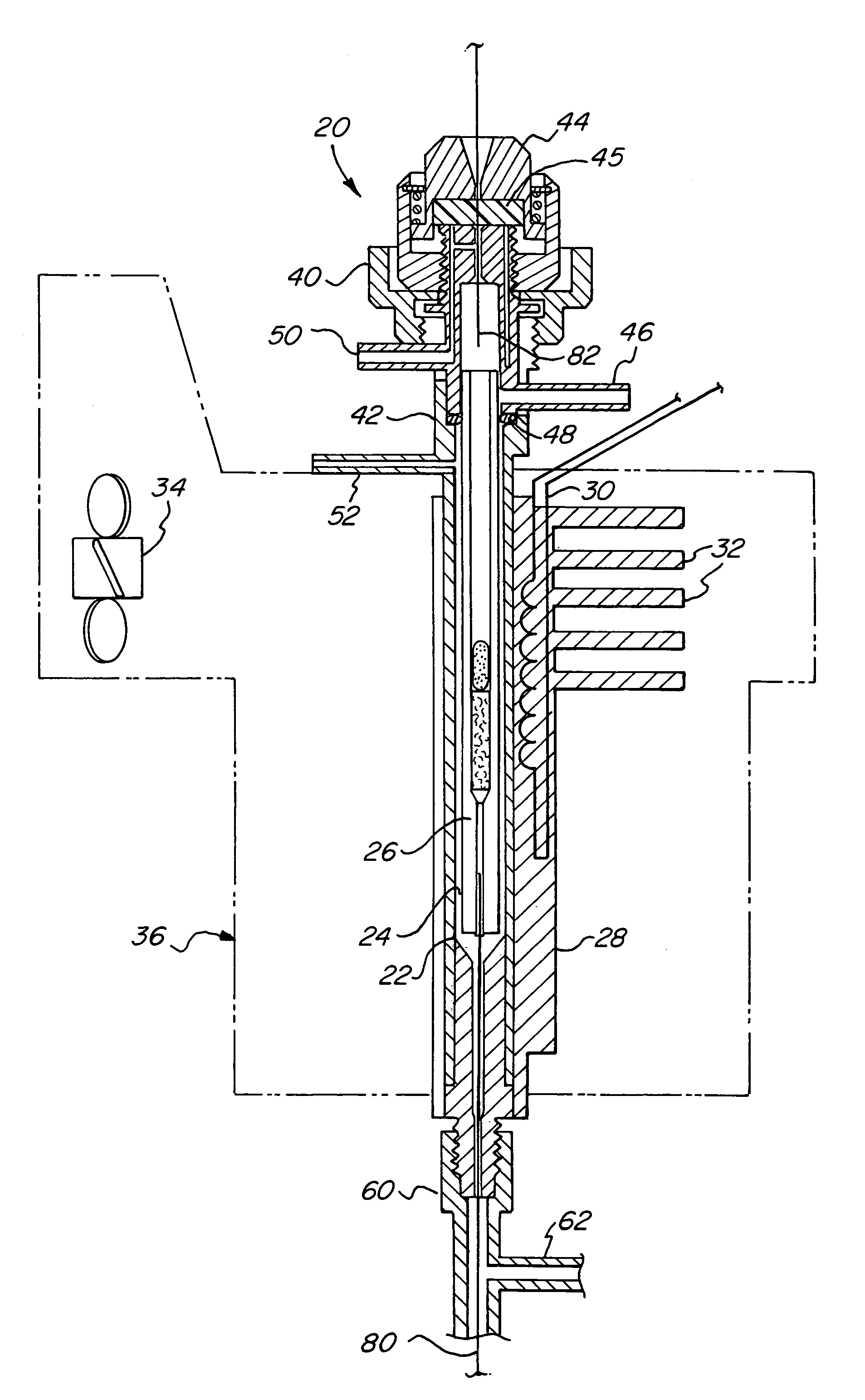
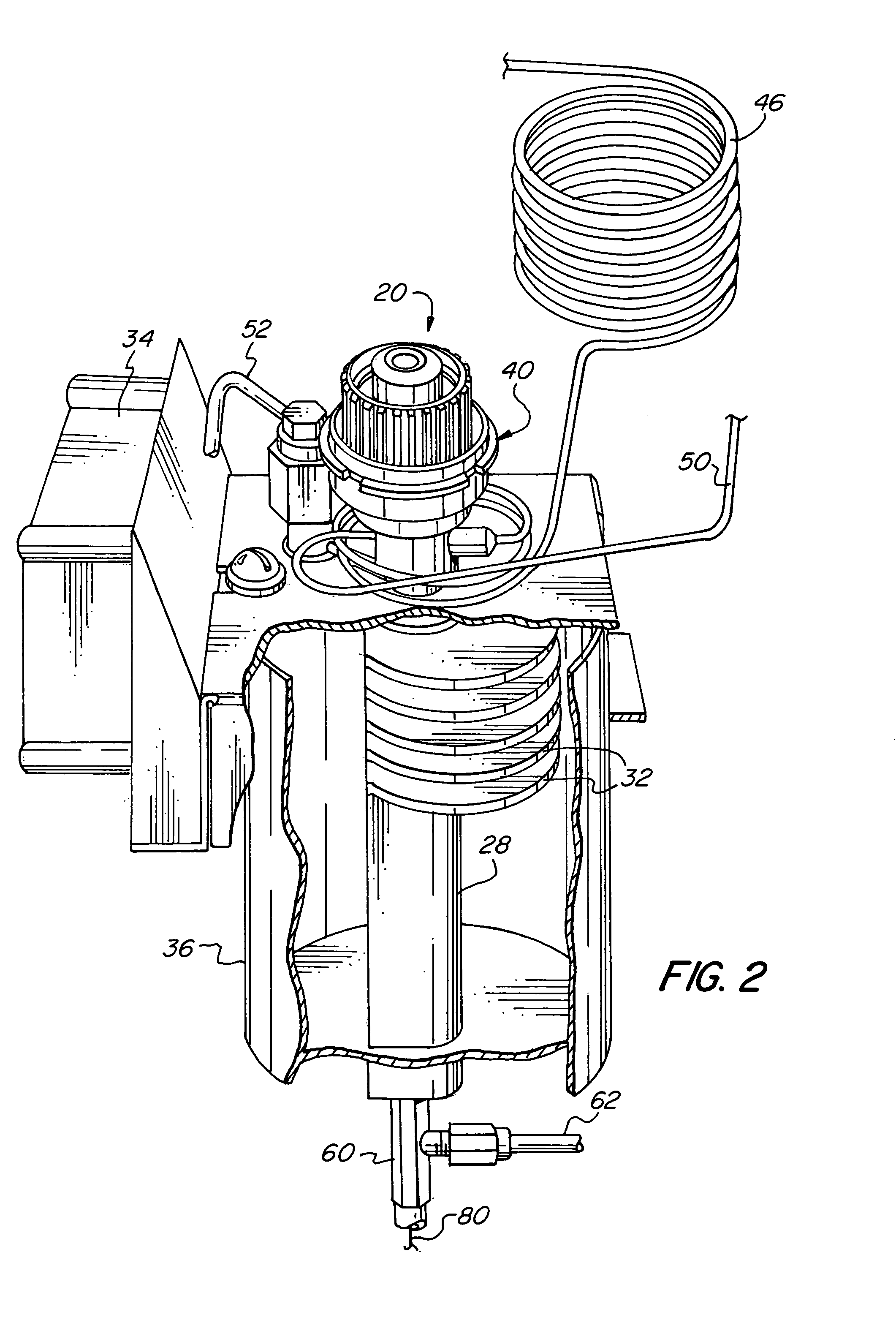
[0034]The basic components of one embodiment of the injector 20, an example of which is the Programmed-Temperature Split / Splitless Inlet System (PSS) Injector manufactured by PerkinElmer Instruments LLC, are illustrated in FIGS. 2 through 3. A metal sleeve 22 cre...


PUM

PropertyMeasurementUnit
diameteraaaaaaaaaa
hydrophobicaaaaaaaaaa
temperatureaaaaaaaaaa

Abstract

An analyte pre-concentrator for gas chromatography is disclosed generally comprising a tube having a restricted outlet and packed with an adsorbent, wherein the tube serves as the liner of a chromatographic injector, as an adsorbent trap coupled to a chromatographic column, and / or as an adsorbent trap coupled to a headspace sampler. Preferably, a heating device allows the tube to be heated. In a preferred embodiment, the analyte pre-concentrator further comprises a column isolating accessory so that a chromatographic column can be temporarily isolated from substances flowing through the tube.

Description

CROSS-REFERENCE TO RELATED APPLICATIONS[0001]This is a continuation of U.S. patent application Ser. No. 10 / 625,259, filed Jul. 22, 2003 now U.S. Pat. No. 6,814,785, which is a continuation of U.S. patent application Ser. No. 10 / 202,147, filed Jul. 24, 2002, now U.S. Pat. No. 6,652,625.FIELD OF THE INVENTION[0002]The present invention relates to a method and apparatus for pre-concentrating analytes and removing moisture in a sample. More specifically, the invention relates to an adsorbent trap for use with chromatographic columns, chromatographic injectors, and headspace samplers.BACKGROUND OF THE INVENTION[0003]Chromatography is essentially a physical method of separation in which constituents of a test sample in a carrier gas or liquid are adsorbed or absorbed and then desorbed by a stationary phase material in a column. A pulse of the sample is introduced into a steady flow of carrier gas. At the end of the column, the individual components are more or less separated in time. Dete...

Claims


Application Information

Patent Timeline
Patent Type & Authority Patents(United States)
IPC IPC(8): G01N1/22G01N30/12
CPCB01D53/025G01N30/12G01N2030/127G01N2030/128G01N2030/085G01N2030/121B01D2253/102G01N2001/2229
Inventor TIPLER, ANDREWCAMPBELL, GARYCOLLINS, MARK
Owner PERKINELMER HEALTH SCIENCES INC
Why Eureka
Try Eureka