Lateral shift measurement using an optical technique

a technology of optical technique and lateral shift, applied in semiconductor/solid-state device testing/measurement, semiconductor/solid-state device details, instruments, etc., to achieve the effect of avoiding confusion

Inactive Publication Date: 2005-12-13
NOVA MEASURING INSTR LTD
View PDF19 Cites 120 Cited by
  • Summary
  • Abstract
  • Description
  • Claims
  • Application Information

AI Technical Summary

Benefits of technology

[0011]Another embodiment of the test structure may contain a two-dimensional grating enabling the measurement of the X and the Y components of the lateral shift at the same site. In order to avoid the possibility to confuse between the X and the Y components several methods may be used: (a) Produce a test site whose period in the Y-axis is signifi

Problems solved by technology

According to this technique, two grating structures of different periodicity are deposited on two adjacent layers in a multi-layer structure,

Method used


Image

  • Lateral shift measurement using an optical technique
  • Lateral shift measurement using an optical technique
  • Lateral shift measurement using an optical technique

Examples


Embodiment Construction

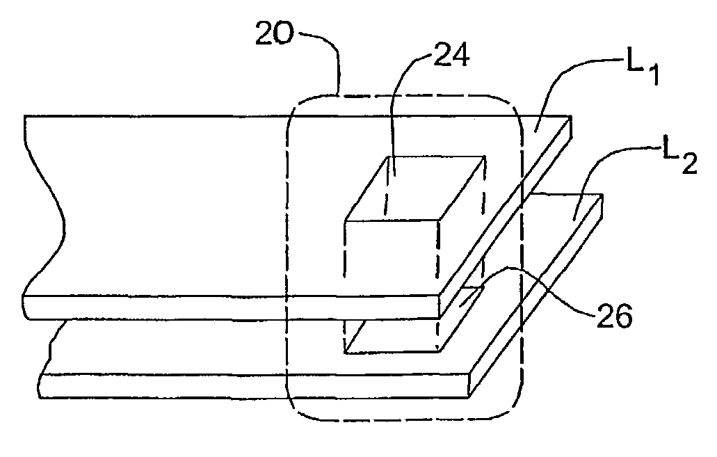
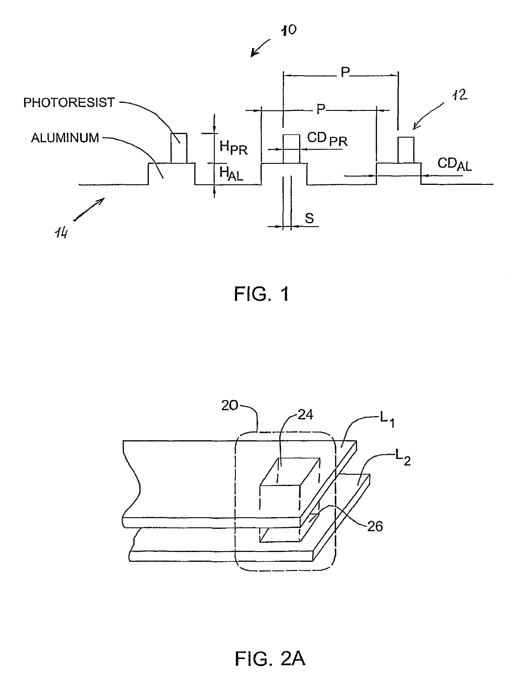
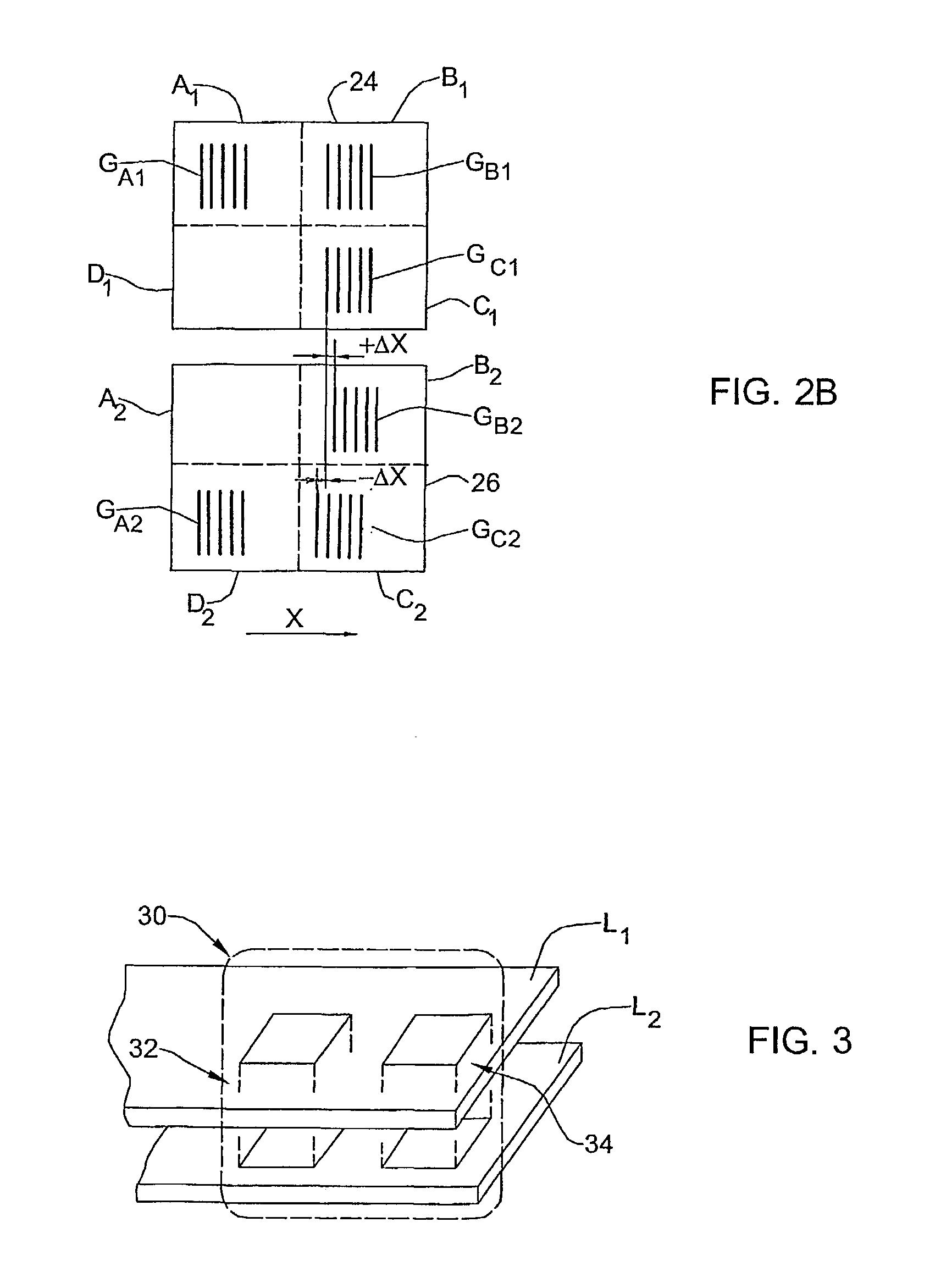
[0018]Referring to FIG. 1, there is schematically illustrated a cross-section of a test site 10 in a semiconductor wafer suitable for use in the present invention. The site 10 contains two gratings (patterned structures) 12 and 14 of certain known periodicity located one above the other. In the present example, the gratings 12 and 14 have substantially the same period P. In the present example, the top grating 12 presents a pattern of spaced-apart photoresist-containing regions RPR, and the underneath grating 14 presents a pattern of spaced-apart aluminum-containing region RAl. In this specific example, the gratings 12 and 14 have different duty cycles defined by features critical dimensions CDPR and DCAl, respectively. It should, however, be noted that this condition is not a requirement for the technique of the present invention, but provides for a better sensitivity of the method. As further shown in the figure, the gratings 12 and 14 are shifted along the X-axis with respect to ...


PUM


Abstract

The method for controlling layers alignment in a multi-layer sample (10), such a semiconductors wafer based on detecting a diffraction efficiency of radiation diffracted from the patterned structures (12, 14) located one above the other in two different layers of the sample.

Description

FIELD OF THE INVENTION[0001]This invention is generally in the field of manufacturing of multi-layer structures, such as semiconductor wafers and integrated circuits, and relates to an optical measuring method and system for control of layers alignment.BACKGROUND OF THE INVENTION[0002]Integrated circuits are multi-layer structures produced by applying a sequence of deposition-lithography-etching steps to a semiconductor wafer. In such structures layers have to be precisely aligned with each other, which is controlled by the so-called “overlay measurement”. This measurement is usually accomplished using a box-within-a-box technique consisting of the following. A rectangular frame-like structure is formed in a test site of each layer, and two adjacent layers are considered as being correctly aligned if a specific alignment between the frames on these layers is provided. Overlay defining the alignment is measured by comparing the shifts between the frames at opposite sides: determining...

Claims


Application Information

Patent Timeline
IPC IPC(8): H01L21/66
CPCG01N21/4788G01N21/9501G01B11/27G03F7/70633H01L22/12G01N21/956G01B11/14
Inventor BRILLFINAROV, MOSHESCHEINER, DAVID
Owner NOVA MEASURING INSTR LTD
Why Eureka
Try Eureka