Method and device for monitoring the direction of rotation of a piston engine

a technology of rotation direction and piston engine, which is applied in the direction of machines/engines, electrical control, instruments, etc., can solve the problems of inability to control the combustion of the cylinder chamber, the risk of damage or destruction of the device in the inlet channel, the intake manifold, etc., and achieve the effect of reliable, timely and simple manner

Inactive Publication Date: 2005-12-13
ROBERT BOSCH GMBH
View PDF7 Cites 35 Cited by
  • Summary
  • Abstract
  • Description
  • Claims
  • Application Information

AI Technical Summary

Benefits of technology

[0006]An object of the exemplary embodiment and / or exemplary method of the present invention is to detect the direction of rotation of a piston engine in a reliable, timely, and simple manner.

Problems solved by technology

A wrong direction of rotation may result, in the case of an internal combustion engine, for example, in a subsequent start attempt remaining fruitless for some time due to the excessively rich fuel-air mixture.
Furthermore, in the event of a wrong direction of rotation there is the risk of damage or destruction of devices in the inlet channel such as, for example, the intake manifold, the throttling device, or a flowmeter.
Should the internal combustion engine rotate in the wrong direction, uncontrolled combustion could occur in a cylinder chamber.
The devices in the inlet channel could become damaged or destroyed due to a return stroke caused by the uncontrolled combustion in the cylinder and by the high exhaust gas temperatures.
In the past, reliable absolute phase angle sensors using the magnetoresistive effect and the Hall effect have been relatively complex components that included at least one control unit and a plurality of sensors.

Method used


Image

  • Method and device for monitoring the direction of rotation of a piston engine
  • Method and device for monitoring the direction of rotation of a piston engine
  • Method and device for monitoring the direction of rotation of a piston engine

Examples


Embodiment Construction

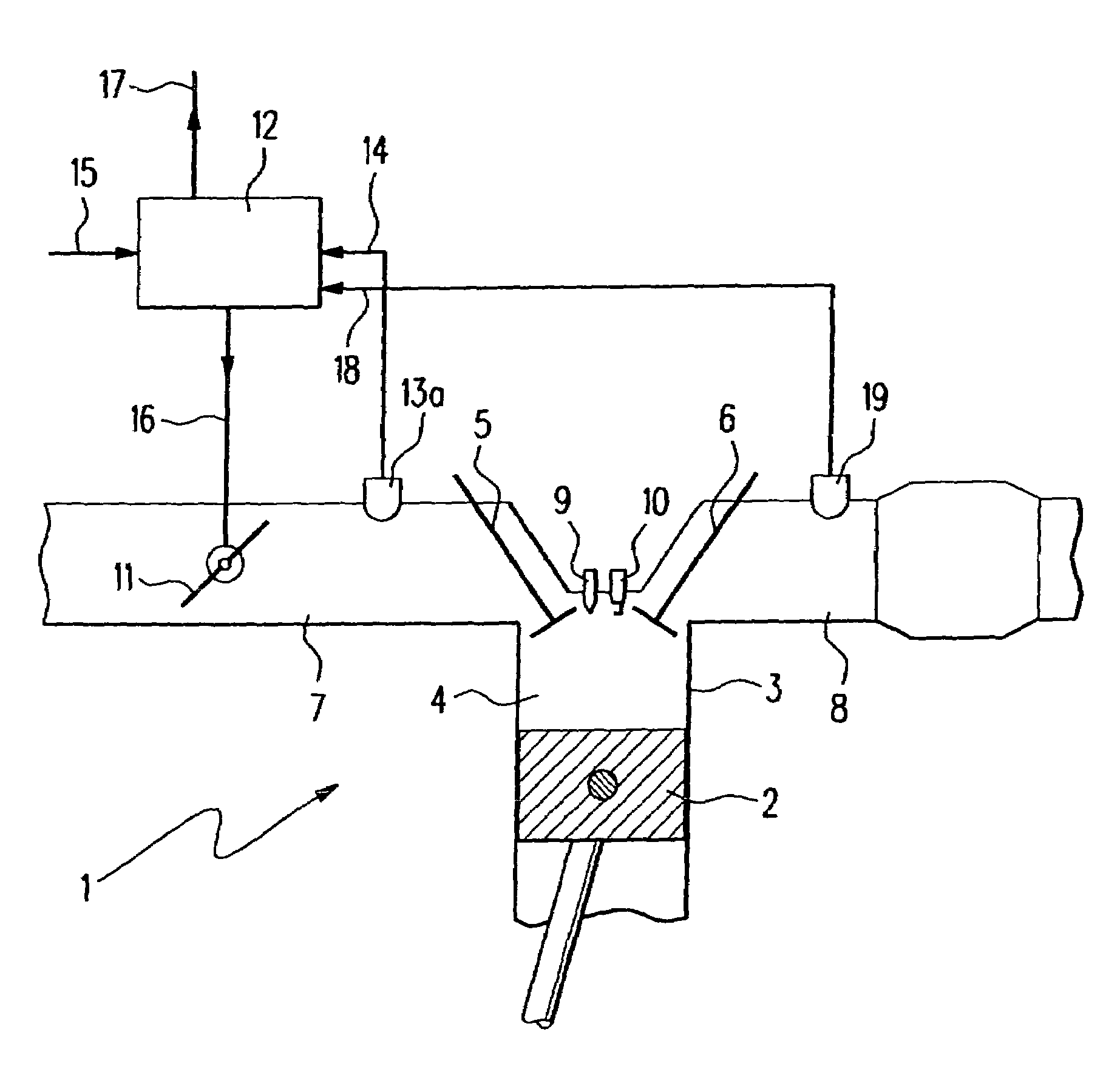
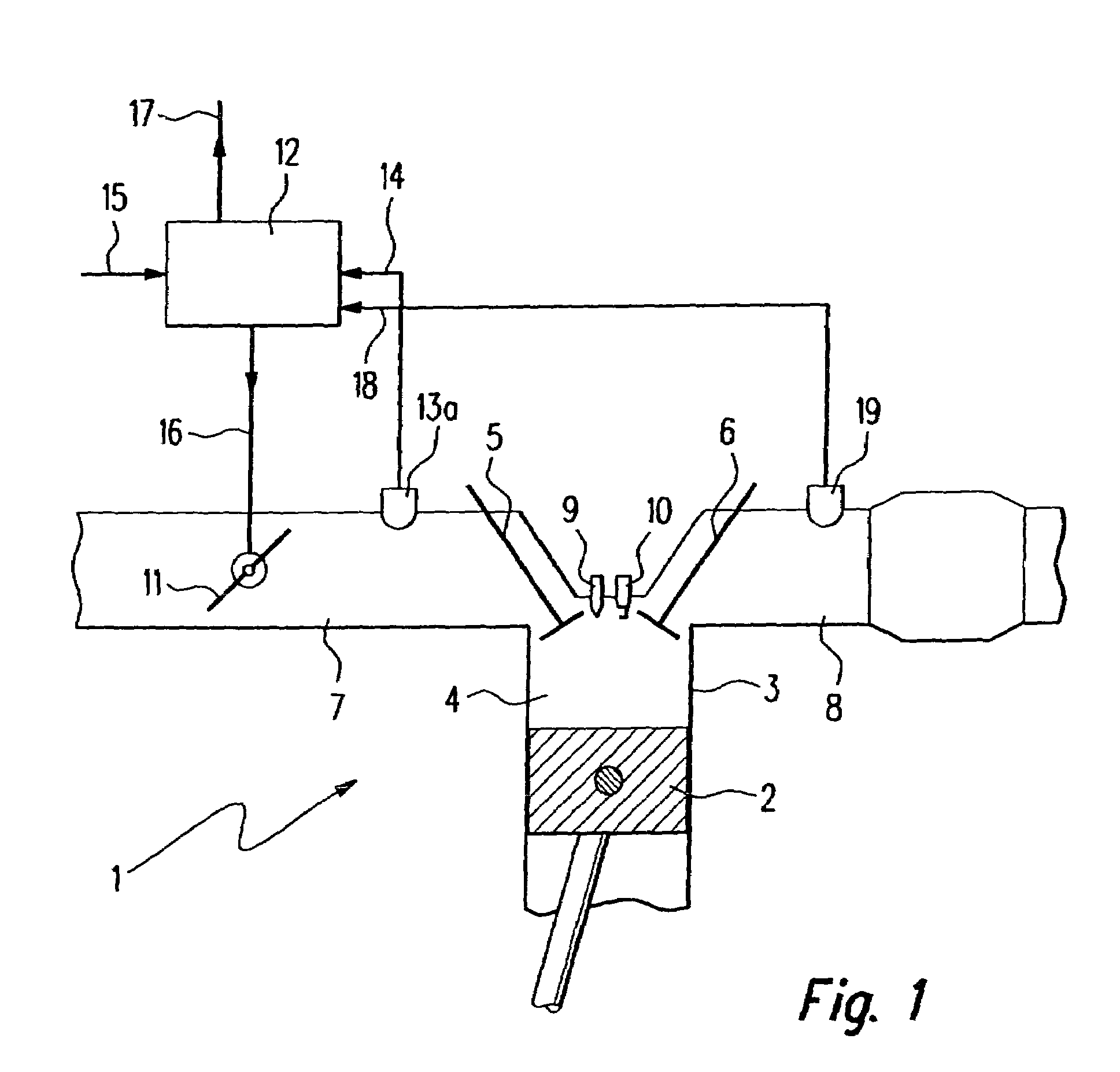
[0028]FIG. 1 shows a piston engine as an internal combustion engine 1 having a control unit 12 for determining the direction of rotation of internal combustion engine 1. Internal combustion engine 1 includes a cylinder 3 in whose internal cylinder chamber a piston 2 is movable back and forth. An inlet valve 5, an outlet valve 6, and an injection nozzle 9 for injecting fuel, and a spark plug 10 for igniting the fuel-air mixture are located on the side of cylinder 3 opposite to piston 2. Inside cylinder 3, a cylinder chamber 4, which in the exemplary embodiment of FIG. 1 is a combustion chamber, is delimited by an inner cylinder wall, piston 2, as well as inlet valve 5 and outlet valve 6.

[0029]An inlet channel 7 opens into combustion chamber 4 via inlet valve 5. A throttling device 11, which is triggerable by a control unit 12 via a control line 16, is mounted in inlet channel 7. Furthermore, a pressure measuring device 13, which may be a pressure sensor, is located in inlet channel 7...


PUM


Abstract

A method and device for detecting the rotation direction of a piston engine, internal combustion engine or piston compressor. The piston engine includes at least one cylinder, a piston movable back and forth in the cylinder, a cylinder chamber formed inside the cylinder which is delimited by an inner cylinder wall and the piston, an inlet channel opening into the cylinder chamber via at least one inlet valve, an outlet channel opening into the cylinder chamber via at least one outlet valve, and at least one triggerable throttling device situated in the inlet channel. To detect the rotation direction in a reliable, timely, and simple manner, the pressure prevailing in the inlet channel is measured when a rotary motion is detected, compared with a predefinable threshold value, and the rotation direction is determined based on the comparison result, the throttling device being closed at least for the pressure measurement time.

Description

FIELD OF THE INVENTION[0001]The present invention relates to a method for detecting the direction of rotation of a piston engine, in particular of an internal combustion engine or of a piston compressor. The present invention also relates to a device for detecting the direction of rotation of a piston engine. Furthermore, the present invention relates to a control unit for controlling and / or regulating a piston engine. The present invention finally also relates to a computer program which is able to run on a computer, in particular on a microprocessor.BACKGROUND INFORMATION[0002]To ensure safe operation of a piston engine, it must be made sure that the piston engine rotates in a predefined direction. A wrong direction of rotation may be triggered in the case of an internal combustion engine, for example, by an erroneous ignition angle output and injection output of a control unit of the engine at start or by a wrong direction of rotation during start as may occur, for example, when ...

Claims


Application Information

Patent Timeline
Patent Type & Authority Patents(United States)
IPC IPC(8): F02D41/02G01P13/04
CPCF02D41/0205F02D41/1448G01P13/04F02D2011/102F02D2200/0406F02D2250/06F02D2400/02
Inventor KOHLER, ROLFKOTTMANN, MATTHIASBAUER, MATTHIAS
Owner ROBERT BOSCH GMBH
Why Eureka
Try Eureka