High-V plate fin for a heat exchanger and method of manufacturing

a heat exchanger and high-v plate technology, applied in indirect heat exchangers, lighting and heating apparatus, laminated elements, etc., can solve the problems of large device and higher, air-side pressure drop, undesirable high pressure drop, etc., to reduce the impact of each segment's thermal wake on the heat transfer capability of downstream segments, the effect of low air-side pressure drop

Inactive Publication Date: 2005-12-20
YORK INT
View PDF23 Cites 32 Cited by
  • Summary
  • Abstract
  • Description
  • Claims
  • Application Information

AI Technical Summary

Benefits of technology

[0012]One advantage of the present invention is the production of a high, air-side, convective heat transfer coefficient and a relatively low air-side pressure drop. The positioning and size of the fin enhancement segments prevent the wake of any one segment from interfering with the heat transfer capabilities of at least the next two downstream segments. The impact of each segment's thermal wake on the heat transfer capability of downstream segments is therefore minimized.
[0013]Another advantage of the present invention is that it minimizes the deleterious impact of fin-surface condensate on heat transfer by promoting gravity-induced drainage of condensate along the fin surface. The first fin segment of each tube row forms a relatively sharp crease, or condensate channel, that spans the entire height of the fin without interruption. Surface tension forms a relatively thick condensate film on the concave side of the crease, where the condensate also happens to be shielded from the viscous drag of the airflow, resulting in relatively large condensate drainage velocities.
[0014]A further advantage of the present invention is that it provides a relatively high airflow face velocity with respect to incipient condensate carryover. If condensate droplets are entrained by the airflow, the sinusoidal shape of the air streamline and the positioning of the fin enhancement segments can redeposit the condensate droplets back on the fin surface within a short airflow travel distance of a fraction of a tube row.
[0015]Still another advantage of the present invention is that it minimizes the pressure drop penalty typically produced by sinusoidal fin enhancement shapes. The division of the fin enhancement into discrete segments that are offset from the LENAS kinematically blocks the development of the secondary flow patterns that tend to form adjacent to curved fluid flow boundaries.
[0016]Other features and advantages of the present invention will be apparent from the following more detailed description of the preferred embodiment, taken in conjunction with the accompanying drawings which illustrate, by way of example, the principles of the invention.

Problems solved by technology

However, increasing the size of the fin leads to a larger device and to a higher, air-side pressure drop, both of which are undesirable.
High pressure drop is undesirable since the energy required to keep air flowing through the coil assembly is proportional to the pressure drop across the coil assembly.
At some point, the cooled air reaches its dew point and is unable to hold moisture as it is cooled further, resulting in condensation on the fin plate.
This mechanism of condensate removal is typically undesirable, since it can lead to problematic biologic activity on downstream surfaces of the equipment housing the coil assembly.
To solve these problems, some fins are produced or manufactured having complex geometries which are difficult and expensive to manufacture.

Method used


Image

  • High-V plate fin for a heat exchanger and method of manufacturing
  • High-V plate fin for a heat exchanger and method of manufacturing
  • High-V plate fin for a heat exchanger and method of manufacturing

Examples


Embodiment Construction

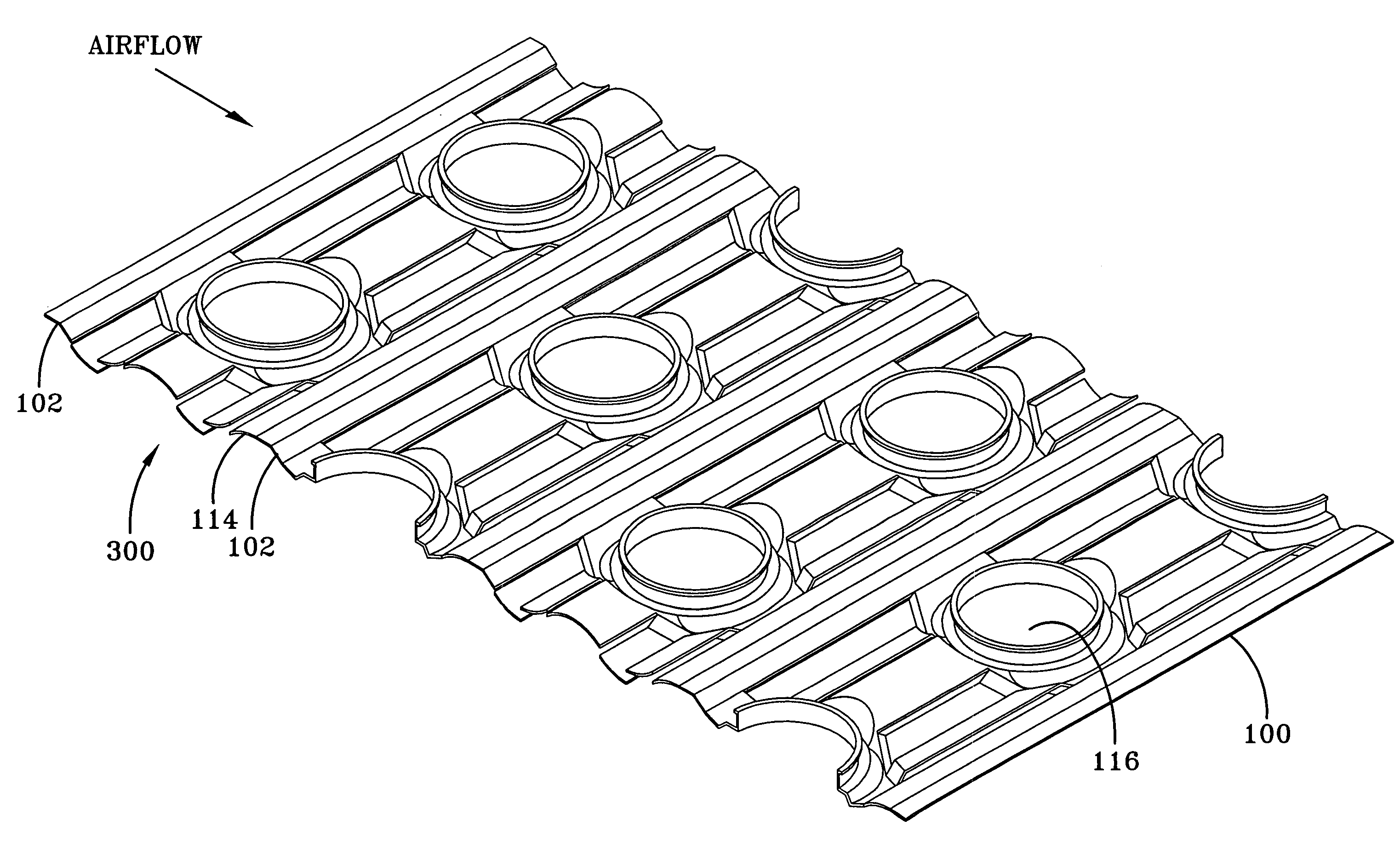
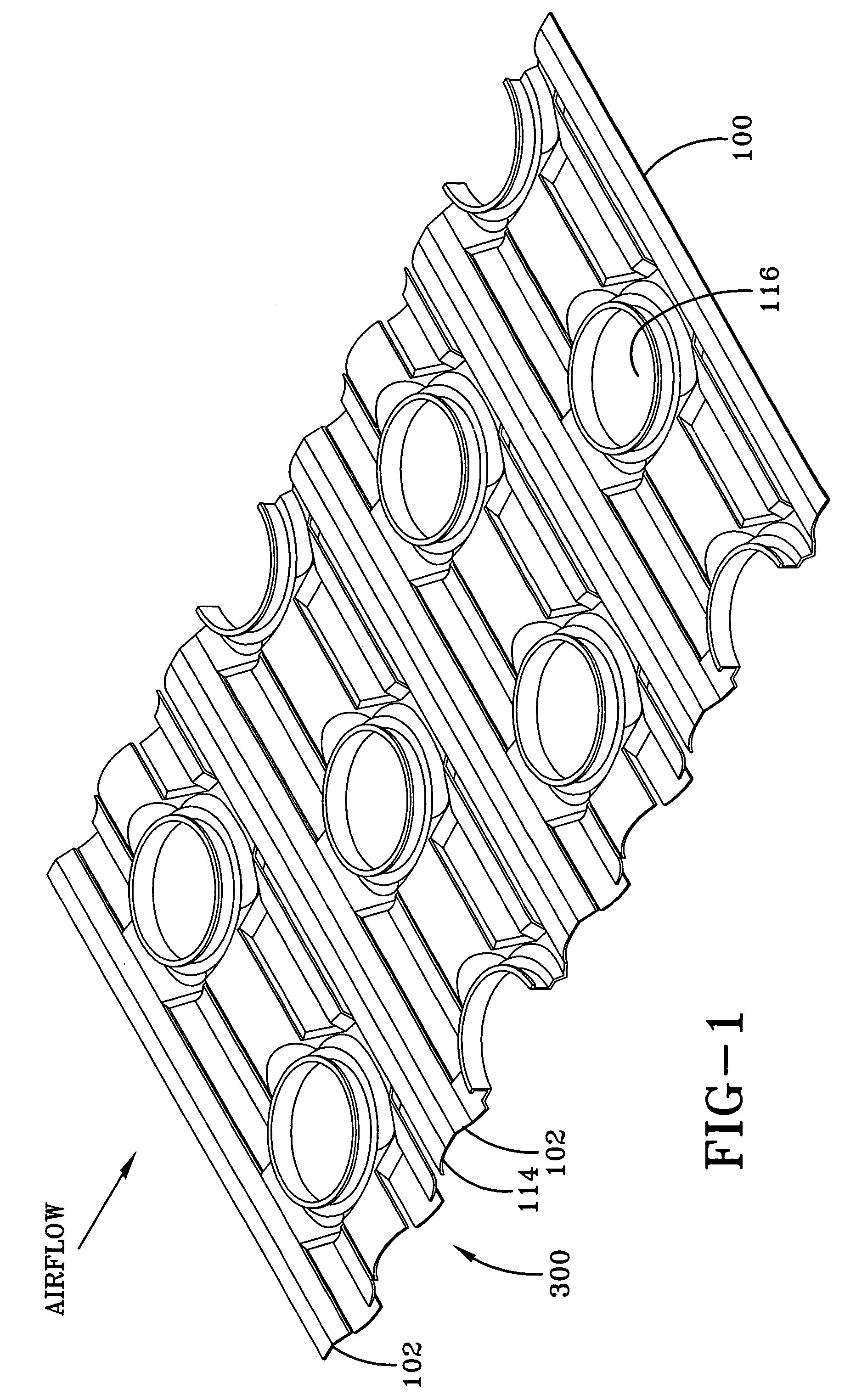
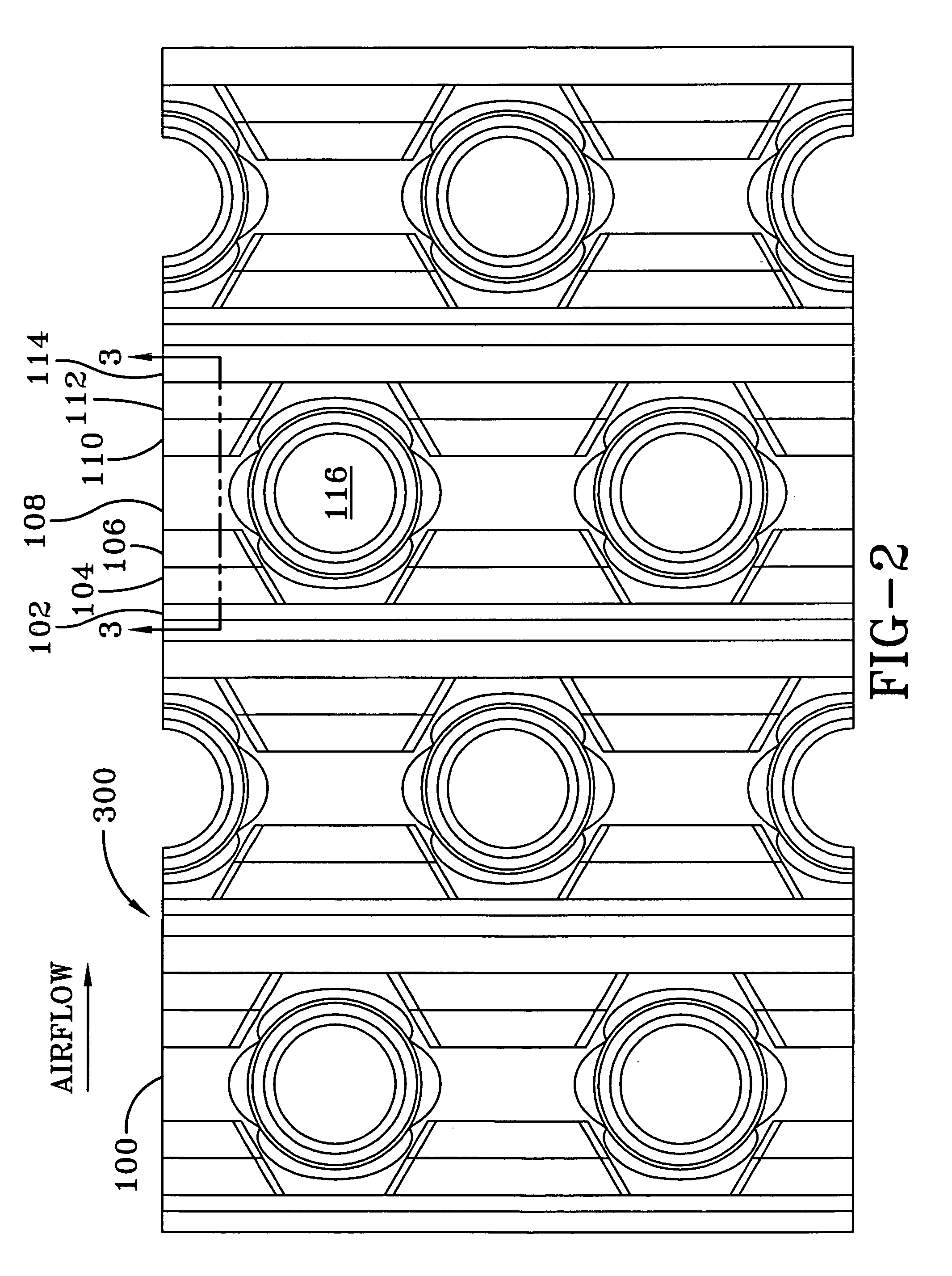
[0030]FIGS. 1 and 2 illustrate one embodiment of a fin 100 having the enhanced heat transfer pattern 300 of the present invention. The fin 100 is preferably incorporated into a heat exchanger, and more preferably a heat exchanger coil assembly, to enhance the heat transfer capabilities of the heat exchanger. The enhanced heat transfer pattern 300 is configured to maximize heat transfer in all areas of the fin 100.

[0031]The enhanced heat transfer pattern 300 has seven distinct and discrete segments 102–114, which segments 102–114 will be described in greater detail below. The segments 102–114 of the enhanced heat transfer pattern 300 are substantially parallel to each row of tubes and can be repeated along the width of the fin 100 an additional number of times, as necessary to correspond to the number of tube rows. The width of the fin 100 is measured in a direction parallel to the direction of airflow through the heat exchanger. The number of times the enhanced heat transfer pattern...


PUM

PropertyMeasurementUnit
angleaaaaaaaaaa
thicknessaaaaaaaaaa
widthaaaaaaaaaa

Abstract

A fin for a heat exchanger coil assembly and a method of manufacturing the fin is provided. The fin includes a heat transfer enhancement pattern which appears sinusoidal in shape. The base wavy pattern of the enhancement pattern includes two wavelengths within each tube row and includes seven discrete segments. Six of the seven segments are circular arc segments. The seventh segment comprises two linear segments which form a condensate channel. The segments are arranged in a particular order at specific distances offset (above and below) from a leading edge nominal air streamline (LENAS) by a fraction of a nominal fin pitch Pf. The LENAS is related to the “normal” base wavy pattern used in other fins.

Description

CROSS-REFERENCE TO RELATED APPLICATIONS[0001]This application claims the benefit of U.S. Provisional Application No. 60 / 301,140 filed Jun. 28, 2001.FIELD OF THE INVENTION[0002]The present invention relates generally to a heat exchanger fin. More specifically, the present invention relates to an enhanced pattern for a plate fin used in a plate fin / tube heat exchanger that maximizes heat transfer in all areas of the fin and a corresponding method of manufacturing the fin to have the enhanced pattern.BACKGROUND OF THE INVENTION[0003]Finned heat exchanger coil assemblies are widely used in a number of applications in fields such as air conditioning and refrigeration. A finned heat exchanger coil assembly generally includes a plurality of spaced parallel tubes through which a heat transfer fluid such as water or refrigerant flows. A second heat transfer fluid, usually air, is directed across the tubes. A plurality of fins is usually employed to improve the heat transfer capabilities of t...

Claims


Application Information

Patent Timeline
Patent Type & Authority Patents(United States)
IPC IPC(8): F28D1/04F28F1/24F28F1/32F28F1/34F28F3/02F28F17/00
CPCF28F1/325F28F17/005Y10T29/4938Y10T29/4935F28F2250/02
Inventor KESTER, DOUGLAS A.
Owner YORK INT
Why Eureka
Try Eureka