Control apparatus and control method for multi-cylinder engine

a control apparatus and multi-cylinder technology, applied in the direction of electric control, machines/engines, output power, etc., can solve the problems of serious aggravating fuel consumption and exhaust emission state, symptom could occur, pre-ignition or misfire to occur in one or more cylinders of the engine, etc., to improve ignitability of mixtures, increase the amount of internal egr, good fuel consumption and exhaust emission characteristics

Inactive Publication Date: 2005-12-20
HITACHI LTD
View PDF3 Cites 23 Cited by
  • Summary
  • Abstract
  • Description
  • Claims
  • Application Information

AI Technical Summary

Benefits of technology

[0016]With the arrangement as described in the foregoing, the control apparatus for a multi-cylinder engine according to the aspect of the present invention can appropriately control the peak value and peak timing of the cylinder pressure for each cylinder. It can thereby suppress variations in the combustion state among different cylinders and different cycles during the engine operation in the compression ignition combustion mode, thus realizing compression ignition combustion offering good fuel consumption and exhaust emissions characteristics.
[0017]Specifically, it is determined whether the peak timing of each cylinder is advanced or retarded in relation to the timing within the predetermined range. If it is determined that the peak timing is advanced, the variable valve is controlled so as to increase the amount of internal EGR, thus improving ignitability of mixtures in all cylinders, that is, advancing the ignition timing. If the engine speed is relatively high (2,000 revolutions per minute or more), however, compression ignition combustion can at times fail due to the amount of intake air being decreased as the internal EGR amount increases. The transmission is therefore controlled so as to slightly decrease the engine speed, thereby increasing the amount of fuel per one cycle for a greater ignitability. If it is determined that the peak timing is retarded, the variable valve is controlled so as to decrease the amount of internal EGR, thereby retarding the ignition timing for all cylinders. At this time, the transmission may be controlled so as to slightly increase the engine speed, thereby decreasing the amount of fuel per one cycle to provide an equivalent power output.
[0018]It is next determined whether or not the peak value of each cylinder falls within the predetermined range. If it is determined that the peak value is lower, the variable valve is controlled so as to increase the amount of internal EGR, thereby improving ignitability of the mixtures of all cylinders, thus allowing a condition, in which heat tends to be generated from combustion, to develop. As noted earlier, if the engine speed is relatively high (2,000 revolutions per minute or more), compression ignition combustion can at times fail due to the amount of intake air being decreased as the amount of internal EGR increases. At this time, therefore, the transmission may also be controlled so as to slightly decrease the engine speed, thereby increasing the amount of fuel per one cycle to provide an equivalent power output.
[0019]A control apparatus for a multi-cylinder engine according to a yet further aspect of the present invention is characterized in the following points. Specifically, the combustion state control means either increases or decreases the amount of fuel supplied from the fuel injection mechanism to each cylinder per one cycle. The fuel injection mechanism is a type that injects fuel directly into the cylinder. The combustion state control means provides control so as to effect at least one fuel injection during a minus overlap period by the variable valve mechanism during the compression ignition combustion mode. If the cylinder-specific combustion state estimating means estimates that the cylinder pressure peak value of at least one cylinder out of the plurality of cylinders is lower than the predetermined value, or the cylinder pressure peak timing of at least one of the plurality of cylinders is retarded in relation to the predetermined timing, the combustion state control means controls the fuel injection mechanism to increase the amount of fuel injected from the mechanism into the cylinder during the minus overlap period. Alternatively, if the cylinder combustion state estimating means estimates that the cylinder pressure peak value of at least one cylinder out of the plurality of cylinders is higher than the predetermined value, or the cylinder pressure peak timing of at least one of the plurality of cylinders is advanced in relation to the predetermined timing, the combustion state control means controls the fuel injection mechanism to decrease the amount of fuel injected from the mechanism into the cylinder during the minus overlap period.
[0020]With the arrangement as described in the foregoing, the control apparatus for a multi-cylinder engine according to the aspect of the present invention can arbitrarily control the condition of the mixture by varying the injection timing or the like according to operating conditions, if the direct fuel injection system is employed. The control apparatus may be applied to a system in which a fuel injection sequence is carried out a plurality of times during the minus overlap period so as to make part of the fuel radical, and the ratio of injection is varied among different cylinders, which allows the apparatus to suppress variations in the combustion state among different cylinders.

Problems solved by technology

If, for example, there are part-to-part variations among those engine components or if any deteriorates, however, a symptom could occur, in which an ignition timing and combustion state vary from one cylinder to another and from one cycle to another even under the same operating conditions.
This symptom could cause pre-ignition or misfire to occur in one or more cylinders of the engine.
There is as a result a problem arising, in which fuel consumption and the state of exhaust emissions are seriously aggravated.
At the same time, even the slightest variations in the cylinder structure greatly affects a combustion condition, which eventually aggravates fuel consumption and the state of exhaust emissions.

Method used


Image

  • Control apparatus and control method for multi-cylinder engine
  • Control apparatus and control method for multi-cylinder engine
  • Control apparatus and control method for multi-cylinder engine

Examples


first embodiment

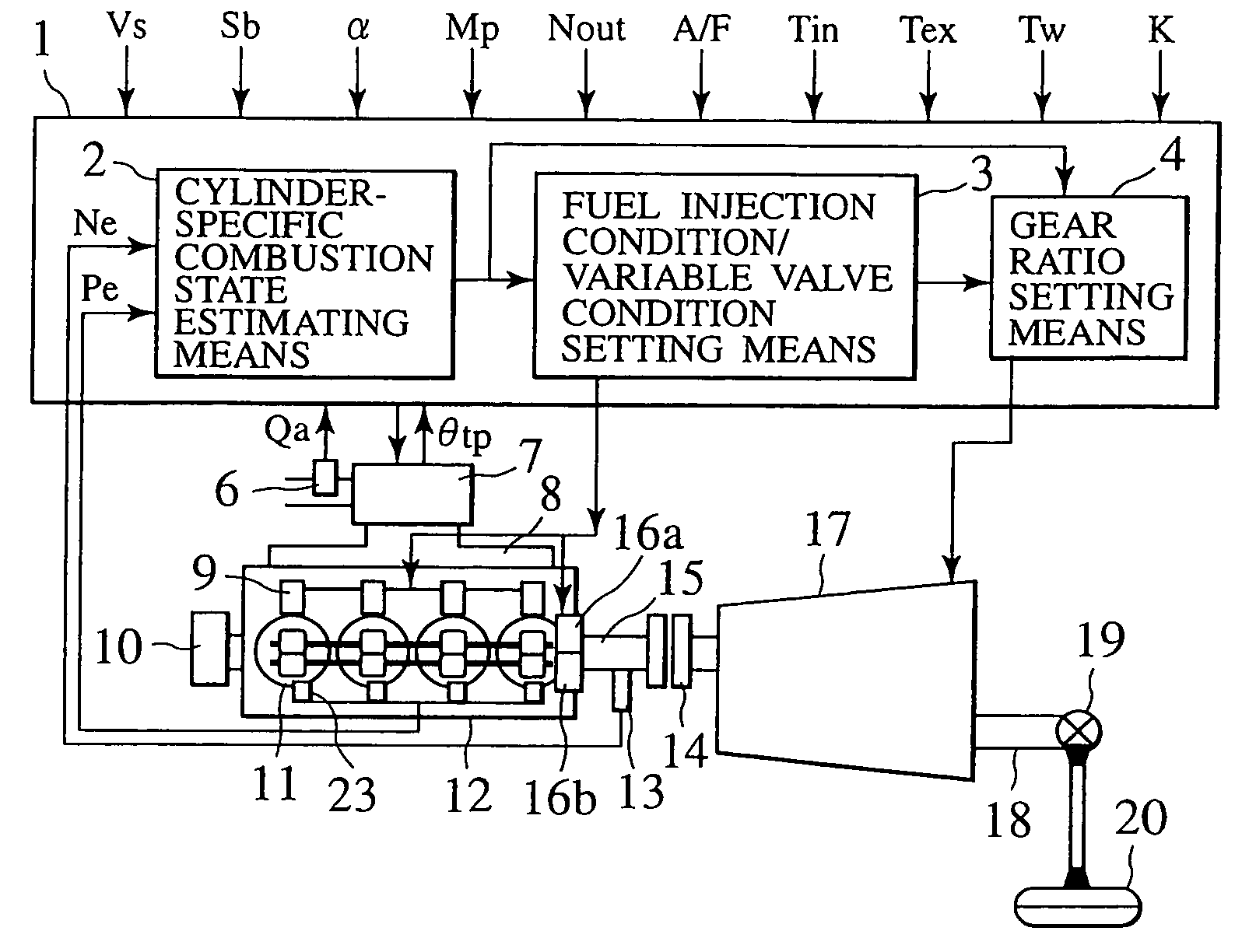
[0039]FIG. 1 is a system configuration diagram showing an engine control apparatus according to the present invention. An engine 12 is a multi-cylinder engine. The multi-cylinder engine 12 is configured so as to carry out combustion in either of two different modes: a spark ignition combustion using an ignition system and a compression ignition combustion, in which a mixture is self-ignited by piston compression.

[0040]Specifically, the multi-cylinder engine 12 is capable of performing a high-efficiency operation using the compression ignition combustion mode in a low-speed, light-load range. More specifically, the range is an engine operating range of up to about a half of full load in terms of an engine torque and about 3,000 revolutions per minute, or rpm, in terms of an engine speed. It performs spark ignition combustion in any other load ranges.

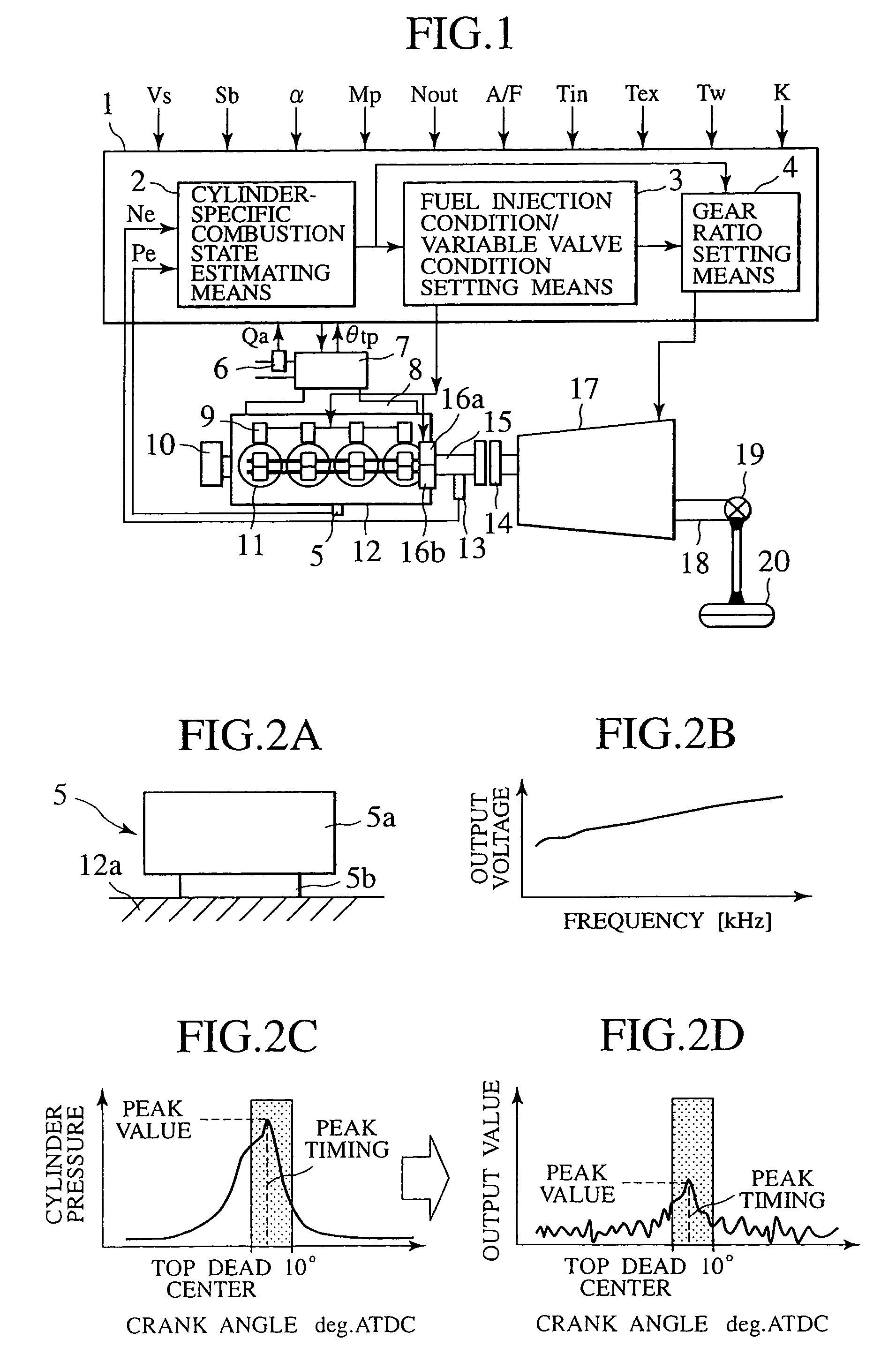
[0041]The engine 12 is provided with a vibration detecting sensor 5 disposed in a cylinder block or a cylinder head that forms a plurali...

third embodiment

[0091]FIG. 9 is a system configuration diagram showing an engine control apparatus according to the present invention. A rotary electric motor (hereinafter referred to as the “motor”) 24 connected by way of gears 25, 27 to the output shaft 15 of the engine is used as the sensor for providing an input signal for the combustion state estimating means for each cylinder. The motor 24 allows the engine torque during the compression ignition combustion mode to be detected highly accurately, allowing the system to estimate the combustion state of each cylinder.

[0092]In addition, the motor is ordinarily capable of assisting in the engine torque as employed in a hybrid vehicle or suppressing variations in torque during gear-shifting or combustion mode switching. It thus offers a great benefit of introduction as a system.

[0093]FIG. 10 is a system configuration diagram showing an engine control apparatus, according to a fourth embodiment of the present invention, mounted on a generator. The ge...

fourth embodiment

[0094]Referring to FIG. 10, the output from the engine 12 is supplied by way of the motor generator 21 and the inverter 22 to an external apparatus as electric power. The PCU 1 reads external information D (such as weather conditions, circuit conditions, power requirements and the like) while the equipment is running. The signal fed from a speed ratio setting means 4a to the inverter 22 is used, at this time, to control the input speed and the output frequency, thereby controlling the engine speed. This allows the combustion state of each cylinder to be estimated and controlled as described earlier. That is, the application of the control apparatus according to the present invention to the generator makes possible equipment operations at high efficiency with low exhaust emissions, just as in the embodiments described heretofore.

[0095]Although the present invention has been described in connection with what are conceived to be practical and preferred embodiments, it is to be understo...


PUM


Abstract

In a multi-cylinder engine having a compression ignition combustion mode, a vibration detecting sensor that is preferably mounted in a cylinder block or a cylinder head is used to detect a frequency and the detected frequency is appropriately analyzed to detect or estimate a cylinder pressure peak value and peak timing for each cylinder. An amount of internal EGR, a fuel injection condition, an engine speed and the like are then controlled so as to bring each of these parameters into an appropriate range thereof. The control apparatus suppresses variations in combustion states among different cylinders and different cycles arising from unit-to-unit variations or deterioration in the engine or part-to-part variations or deterioration in a component thereof.

Description

BACKGROUND OF THE INVENTION[0001]The present invention relates to a control apparatus and a control method for a multi-cylinder engine and, more particularly, to a control apparatus and a control method for a multi-cylinder engine that suppresses, in a favorable manner, variations in an ignition combustion state among different cylinders during an engine operation in a compression ignition combustion mode.[0002]There is known a multi-cylinder engine that works on a combustion principle, in which a premixture is compressed and self-ignited. This type of engine is, what is called, a homogeneous charge compression ignition combustion multi-cylinder engine. It is desired that this type of engine be controlled in a favorable manner so that it performs a self-ignition combustion that exhibits high efficiency over a wide operating range. For example, Japanese Patent Laid-open No. 2000-320333 discloses a technique, in which valve timing of intake and exhaust valves are controlled so as to p...

Claims


Application Information

Patent Timeline
Patent Type & Authority Patents(United States)
IPC IPC(8): B60K6/20F02B1/12F02B11/00F02B13/06F02D13/02F02D21/08F02D29/00F02D35/02F02D41/00F02D41/02F02D41/04F02D41/30F02D41/34F02D43/00F02D45/00F02P5/00
CPCF02B1/12F02D13/0207F02D13/0265F02D35/023F02D35/028F02D41/006F02D41/008F02D41/3035F02D41/3076B60K2741/045Y10T477/688F02D2041/001F02D2041/288Y02T10/52Y02T10/18Y02T10/47Y10T477/675Y10T477/68B60W2710/0616B60W10/04B60W10/10B60W30/1819Y02T10/84Y02T10/12Y02T10/40F02D13/02
Inventor YAMAOKA, SHIRONOGI, TOSHIHARUSHIMADA, ATSUSHIKANEKAWA, NOBUYASUIIHOSHI, YOUICHI
Owner HITACHI LTD
Why Eureka
Try Eureka