Maintaining the alignment of electric and magnetic fields in an x-ray tube operated in a magnetic field

a magnetic field and x-ray tube technology, applied in the field of imaging systems, can solve the problems of inability to use the mri system, inability to move the patient, inconsistent images,

Inactive Publication Date: 2005-12-20
THE BOARD OF TRUSTEES OF THE LELAND STANFORD JUNIOR UNIV
View PDF19 Cites 43 Cited by
  • Summary
  • Abstract
  • Description
  • Claims
  • Application Information

AI Technical Summary

Benefits of technology

[0015]Accordingly, it is a primary object of the present invention to provide an x-ray tube that can be operated in the presence of a high magnetic field without being inadvertently affected thereby. The goal is achieved by providing inventive methods and apparatuses for controlling and / or maintaining the alignment of electric and magnetic fields. The inventive methods and apparatuses eliminate magnetic field components transverse to the principal desired direction of travel of the electron beam in the x-ray tube.

Problems solved by technology

Moving the patient is undesirable, because it is time consuming, possibly dangerous, and can render the images inconsistent.
For example, conventional x-ray fluoroscopy detectors are image intensifiers, which are exceedingly sensitive to magnetic fields and therefore cannot be used near, let alone inside, an MRI system.
A major obstacle to combining MRI and x-ray systems is the x-ray source, which consists of an x-ray tube and its housing.
Thus the effect of the static magnetic field of the MRI system on the x-ray tube can be highly undesirable and may damage the tube if it is operated under non-ideal conditions, or it may lower the x-ray intensity to a level that is unacceptable.
In the combined system, it is not desirable—indeed it may be impossible—to turn off the static magnetic field before acquiring x-ray images, and so the effect of the magnetic field on the x-ray tube must be addressed.
This technique, however, limits the system in that the x-ray tube must remain fixed at a certain orientation and / or distance with respect to the static magnet.
Moreover, Meulenbrugge et al's invention does not teach or suggest how to control / maintain the alignment of the electric and magnetic fields in the x-ray tube.
Sufficient cladding to completely eliminate the effect of the magnetic field on the electron beam may not be feasible.
Aligning the tube with the magnetic field also has potential problems including that the type and / or the placement of the x-ray tube may be limited and that it may be difficult to rotate the x-ray tube to different orientations around the patient.
X-ray tube inserts typically have components that distort the magnetic field and pose additional difficulties.
More importantly, since such alignment has a very small tolerance, it is critically difficult to attain.
If a correct amount of current is applied to the coils, the coils will generate magnetic fields that exactly oppose the transverse components of the external field, causing cancellation.

Method used


Image

  • Maintaining the alignment of electric and magnetic fields in an x-ray tube operated in a magnetic field
  • Maintaining the alignment of electric and magnetic fields in an x-ray tube operated in a magnetic field
  • Maintaining the alignment of electric and magnetic fields in an x-ray tube operated in a magnetic field

Examples


Embodiment Construction

[0023]Although the following detailed description contains many specifics for the purposes of illustration, anyone of ordinary skill in the art will appreciate that many variations and alterations to the following details are within the scope of the invention. Accordingly, the following embodiments of the invention are set forth without any loss of generality to, and without imposing limitations upon, the claimed invention.

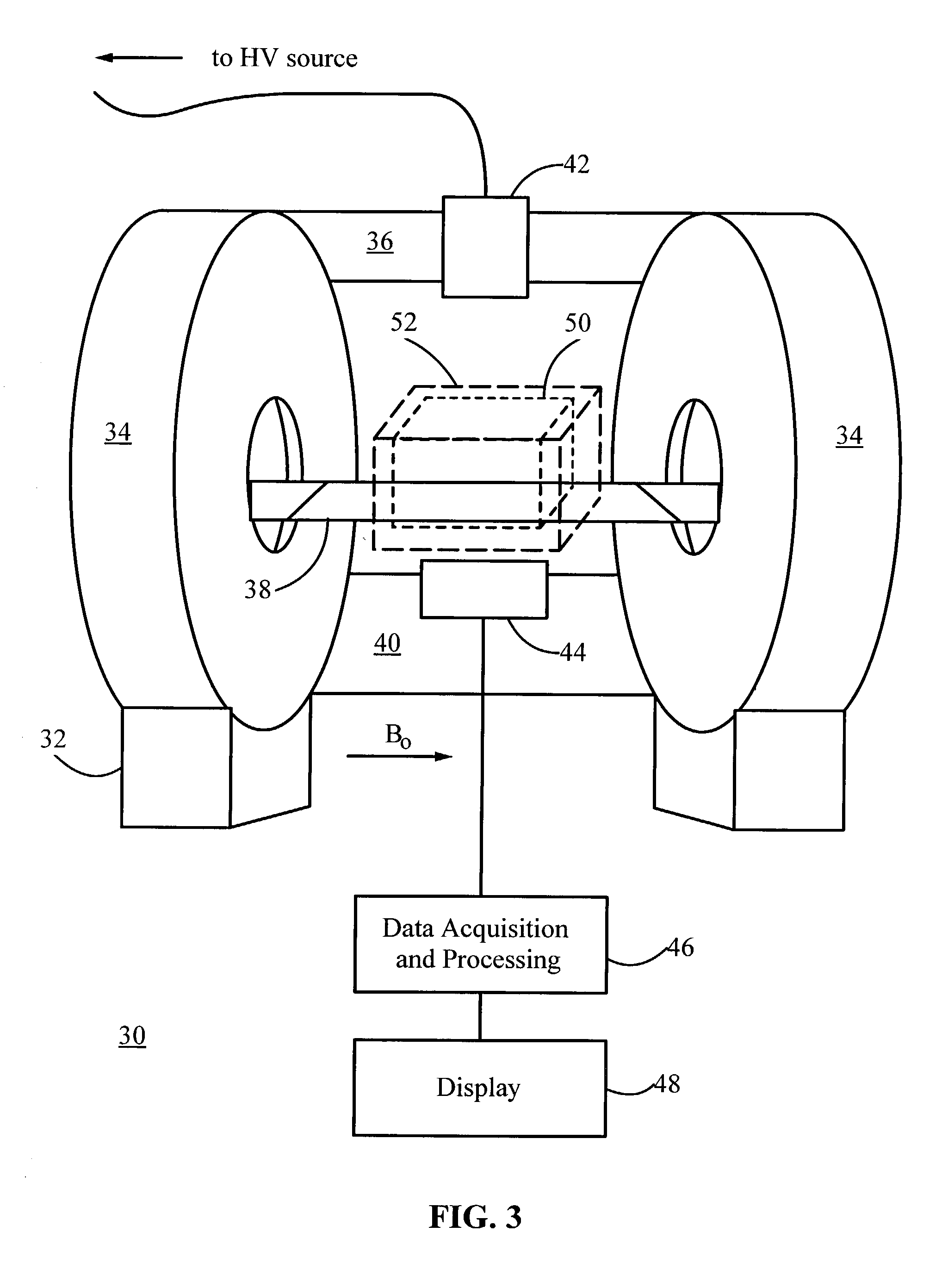
[0024]The present invention provides a combined magnetic resonance imaging (MRI) and x-ray fluoroscopic imaging apparatus and method. Ideally, the two imaging systems have substantially coincident fields of view (FOV). This allows both types of images to be acquired without moving the object being imaged (e.g., a patient). The invention is particularly advantageous for image-guided interventional procedures, in which x-ray imaging guides placement of guidewires, catheters, or stents, while MR imaging provides soft tissue contrast. Conventional individual systems a...


PUM


Abstract

A new technique for maintaining the alignment of electric and magnetic fields in an x-ray tube so the tube can be operated in the presence of a static external magnetic field without being negatively affected thereby. Deflection of the electron beam of the x-ray tube by the high magnetic field is reduced or eliminated by modifying or canceling, at a location near the electron beam, the magnetic field components transverse to the beam. In a preferred embodiment, a set of electromagnet coils are positioned on or near the tube and oriented in a way that when current is applied internal magnetic fields are produced in a direction opposite to the transverse magnetic fields, thereby causing cancellation. In one implementation, one or more sensors are used to detect the transverse magnetic fields. The sensor is positioned near the electron beam, either inside or outside the x-ray tube. The sensor produces a signal dependent on a static magnetic field component transverse to the desired direction of the electron beam. This signal is used to control the amount of current applied to the coils. A controller and a feedback circuit may be included to adjust in real time the amount of current being applied.

Description

CROSS-REFERENCE TO RELATED APPLICATIONS[0001]This is a continuation-in-part application of an earlier filed non-provisional application Ser. No. 09 / 823,889, filed Mar. 30, 2001, which claims the benefit of U.S. Provisional Application Nos. 60 / 193,731 and 60 / 193,735, both filed Mar. 30, 2000.STATEMENT REGARDING FEDERALLY SPONSORED RESEARCH OR DEVELOPMENT[0002]This invention was supported in part by grant number P41 RR09784 from the National Institutes of Health (NIH). The U.S. Government has certain rights in the invention.FIELD OF THE INVENTION[0003]This invention relates generally to imaging systems and methods, for example, for medical imaging and non-destructive testing, combining magnetic resonance imaging (MRI) and x-ray imaging in the same location. More particularly, it relates to an improved technique for controlling and maintaining the alignment of electric and magnetic fields in an x-ray tube operated in the presence of a magnetic field.BACKGROUND ART[0004]Magnetic resonan...

Claims


Application Information

Patent Timeline
Patent Type & Authority Patents(United States)
IPC IPC(8): H01J35/14H01J35/16H05C1/02
CPCH01J35/14H01J35/16H05C1/02G01R33/4812
Inventor PELC, NORBERT J.
Owner THE BOARD OF TRUSTEES OF THE LELAND STANFORD JUNIOR UNIV
Why Eureka
Try Eureka