Method and apparatus for generating a membrane target for laser produced plasma

a laser and plasma technology, applied in the direction of x-ray tubes, beam/ray deflecting arrangements, optical radiation measurement, etc., can solve the problems of limited range of desired wavelengths achievable by either gas or liquid systems, strong shocks into solid materials, and impose limitations on chemical elements or materials. , to achieve the effect of easy illumination, less debris and splashing, and convenient illumination

Inactive Publication Date: 2005-12-20
JMAR LLC A DELAWARE LLC
View PDF1 Cites 6 Cited by
  • Summary
  • Abstract
  • Description
  • Claims
  • Application Information

AI Technical Summary

Benefits of technology

[0008]A method and apparatus for generating membrane targets for a laser-induced plasma is disclosed herein. Membranes are advantageous targets for laser induced plasma because they are very thin and can be readily illuminated by high-power coherent light, such as a laser, and converted into plasma. Membranes are also advantageous because illumination of the membrane with coherent light produces less debris and splashing than illumination of a thicker, solid target. Spherical membranes possess additional advantages in that they can be readily illuminated from variety of directions and because they can be easily placed (i.e., blown) into a target region for illumination by coherent light. Membranes are also advantageous because they can be formed from a liquid or molten phase of the target material. According to another embodiment, membranes can be formed from an inert solution in which the target materials are solvated. Membranes can be formed in a variety of ways, such as rotating a circular apparatus through a reservoir of liquid target material such that membranes form across apertures that are disposed in the circular apparatus. Spherical membranes can also be formed by applying a gas (i.e., blowing) against a membrane formed in an aperture of a circular apparatus.

Problems solved by technology

Current systems that use either room temperature liquid or gas targets impose limitations on the type of chemical elements or materials that can be irradiated because many elements are not in the liquid or gaseous state at ambient pressure and temperature.
Hence, the range of desired wavelengths achievable by either gas or liquid systems is also limited.
These extreme temperatures and pressures cause ion ablation and send strong shocks into the solid material.
Ion ablation from the surface of the target material at very high speeds and temperatures causes contamination within the radiation chamber as well as to other system equipment such as the radiation collection system and the optics associated with the laser.
Ion ablation and target debris decrease the efficiency of the system, increase replacement costs, and shorten the lifetime of the optical and laser equipment.
Unfortunately, the use of a thin tape target does not completely eliminate target debris at the laser focal point of the target tape.
Unfortunately, significant amounts of target debris can still be produced in cooler portions of the laser beam.
Moreover, this system does not provide mechanisms that deflect target debris away from optics, and other expensive equipment used in generating radiation.
Current systems and methods utilizing thin tape targets suffer additional disadvantages.
The types of materials that are commercially available in thin tape form are extremely limited.
Further, thin tape targets require a large tape-dispensing apparatus, which utilizes a significant amount of space within the x-ray chamber, substantially adding to the size and space requirements of such x-ray generators.
Tape targets also require frequent reloading of new tape material, which disrupts the operation of the x-ray generator.

Method used


Image

  • Method and apparatus for generating a membrane target for laser produced plasma
  • Method and apparatus for generating a membrane target for laser produced plasma
  • Method and apparatus for generating a membrane target for laser produced plasma

Examples


Embodiment Construction

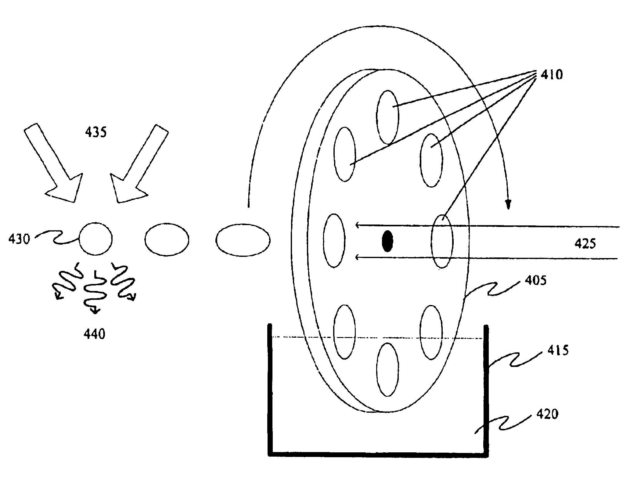
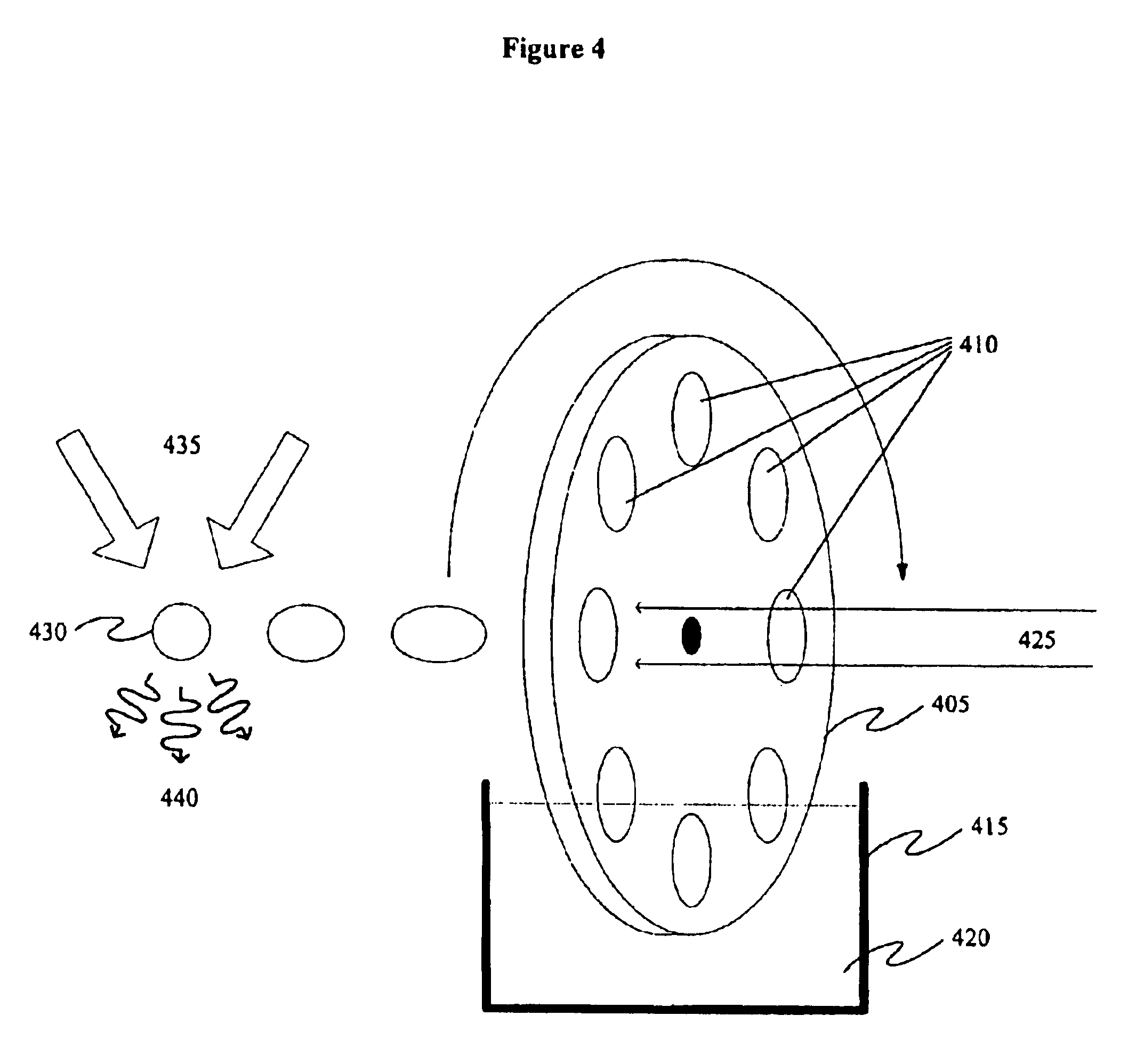
[0022]A method and apparatus for generating membrane targets for laser-produced plasma are described and depicted below. As stated previously, it is desirable to utilize a target in the shape of a thin disc. Accordingly, a thin membrane comprising the desired substance may be utilized as an approximation of the thin disc, thereby providing a desirable target material. Alternatively, a spherical membrane may be used to approximate a thin disc. Spherical membranes possess the advantage that they may be illuminated with coherent light from more than one direction. These embodiments, as well as the devices used to produce them, are described in further detail below.

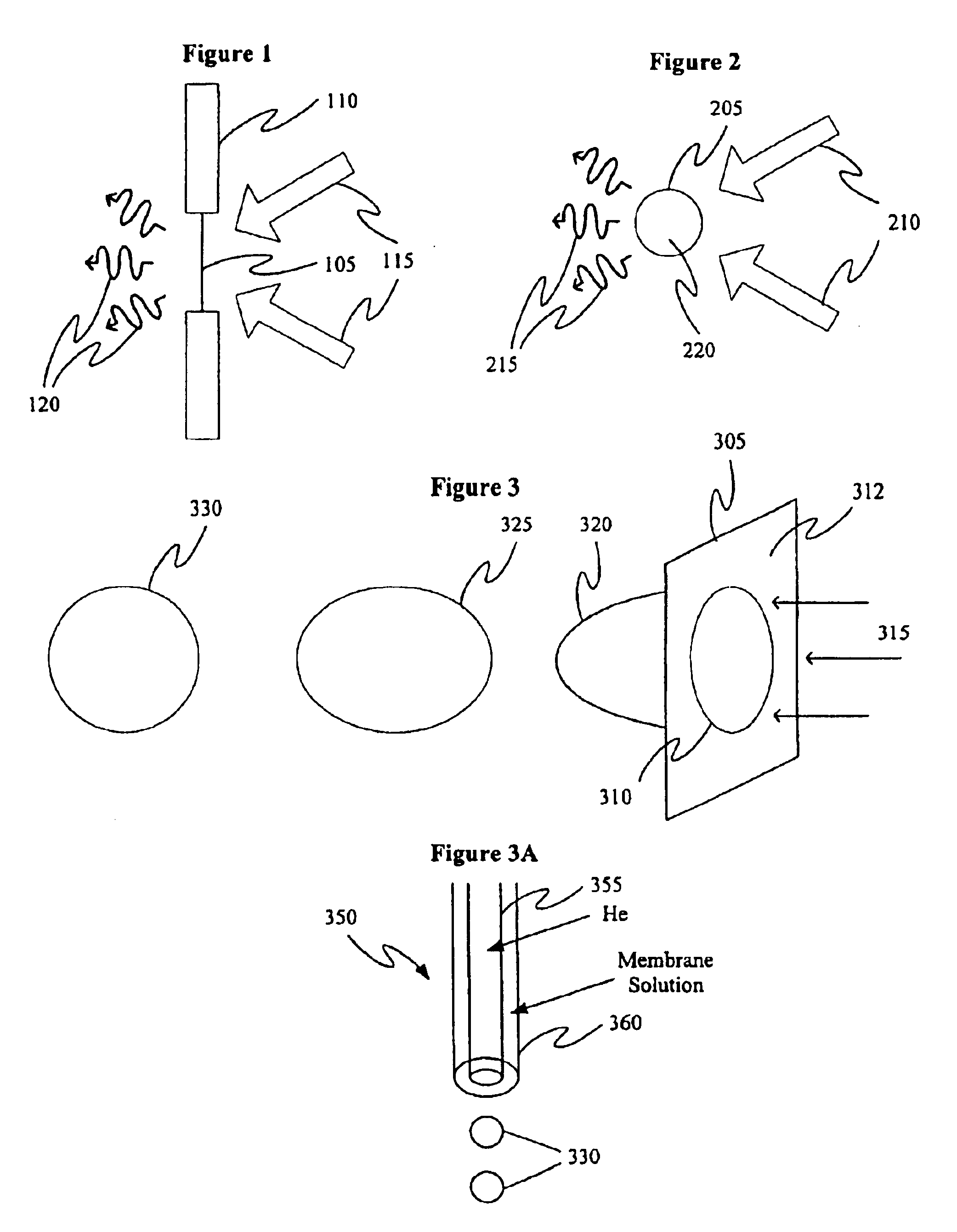
[0023]A cross-sectional view of one embodiment of a membrane apparatus for laser-produced plasma is depicted in FIG. 1. In FIG. 1, a target membrane 105 is formed in an aperture in a membrane apparatus 110 and is held in place by virtue of the surface tension of the membrane material 105. The membrane is illuminated with cohe...


PUM


Abstract

A method and apparatus for generating membrane targets for a laser induced plasma is disclosed herein. Membranes are advantageous targets for laser induced plasma because they are very thin and can be readily illuminated by high-power coherent light, such as a laser, and converted into plasma. Membranes are also advantageous because illumination of the membrane with coherent light produces less debris and splashing than illumination of a thicker, solid target. Spherical membranes possess additional advantages in that they can be readily illuminated from variety of directions and because they can be easily placed (i.e. blown) into a target region for illumination by coherent light. Membranes are also advantageous because they can be formed from a liquid or molten phase of the target material. According to another embodiment, membranes can be formed from a solution in which the target materials are solvated. Membranes can be formed an a variety of ways, such as by rotating a circular apparatus through a reservoir of liquid target material such that membranes form across apertures that are disposed in the circular apparatus. Spherical membranes can also be formed by applying a gas (i.e. blowing) against a membrane formed in an aperture of a circular apparatus.

Description

[0001]This application claims benefit of 60 / 437,647 filed Jan. 2, 2003.BACKGROUND[0002]Various methods and systems are known for generating short wavelength radiation. For example, x-rays may be generated by striking a target material with a form of energy such as an electron beam, a proton beam, or a light source such as a laser. Extreme ultraviolet radiation (EUV) may also be generated in a similar manner. Various forms of short-wavelength radiation generating targets are known. These known systems and methods typically irradiate gases, liquids, frozen liquids, or solids to generate the short-wavelength radiation. Current systems that use either room temperature liquid or gas targets impose limitations on the type of chemical elements or materials that can be irradiated because many elements are not in the liquid or gaseous state at ambient pressure and temperature. Hence, the range of desired wavelengths achievable by either gas or liquid systems is also limited.[0003]Solid mater...

Claims


Application Information

Patent Timeline
Patent Type & Authority Patents(United States)
IPC IPC(8): G21K1/00H01J3/00H05G2/00H05H1/00H05H6/00
CPCG03F7/70033G03F7/70825G03F7/70916H05G2/00H05G2/001H05G2/005
Inventor RIEGER, HARRY R.TURCU, I. C. EDMONDMORRIS, JAMES
Owner JMAR LLC A DELAWARE LLC
Why Eureka
Try Eureka