Method for spectral analysis, and scanning microscope

a spectral analysis and scanning microscope technology, applied in the field of spectral analysis and scanning microscope, can solve the problems of insufficient sensitivity of downstream line detectors, insufficient spectral resolution of apparatuses in which spectrometers are provided, and insufficient spectral resolution of apparatuses, etc., to achieve rapid and efficient spectral analysis, high spectral resolution, and good sensitivity dynamics

Inactive Publication Date: 2005-12-20
LEICA MICROSYSTEMS CMS GMBH
View PDF10 Cites 14 Cited by
  • Summary
  • Abstract
  • Description
  • Claims
  • Application Information

AI Technical Summary

Benefits of technology

[0012]It is therefore the object of the invention to propose a method for spectral analysis of the light proceeding from a specimen that on the one hand offers the possibility of high spectral resolution and good sensitivity dynamics, and on the other hand makes possible rapid and efficient spectral analysis over a definable spectral region.
[0019]A further object of the invention is to describe a scanning microscope that on the one hand offers the possibility of high spectral resolution and good sensitivity dynamics, and on the other hand makes possible rapid and efficient spectral analysis over a definable spectral region.
[0021]The invention has the advantage that the light proceeding from a specimen can be analyzed in such a way as to make possible rapid and efficient acquisition of entire spectra with no need for the user to accept the disadvantages exhibited by spectrometers.
[0032]In contrast to a dielectric main beam splitter for separation of the excitation and detection beam paths, which always exhibits a very particular transmission characteristic for the detected light and thus results in distortion of the emission spectrum, an acoustooptical component can be adapted almost ideally to the excitation and emission wavelengths. The acoustooptical component is almost completely transparent at all emission wavelengths, except that a spectral window of only approx. 2 nm is cut out for the excitation wavelengths. The excitation wavelength can be suppressed in the detection beam path so effectively that spectral regions can be placed almost in the immediate spectral vicinity of the excitation wavelength without allowing excitation light to enter the detectors.

Problems solved by technology

The known methods and apparatuses are of only limited suitability for spectral analysis of the light proceeding from a specimen and for the acquisition of entire spectra that are e.g. several tens or several hundreds of nanometers wide, and exhibit critical disadvantages for these applications.
The apparatuses in which spectrometers, in particular grating spectrometers, are provided often have insufficient spectral resolution especially for fluorescence microscopy applications.
This is usually attributable to unavoidable scattering of light at the grating structures.
Apparatuses that contain prism spectrometers having downstream line detectors, for example photodiode arrays, exhibit insufficient dynamics in terms of detection sensitivity.

Method used


Image

  • Method for spectral analysis, and scanning microscope
  • Method for spectral analysis, and scanning microscope
  • Method for spectral analysis, and scanning microscope

Examples


Embodiment Construction

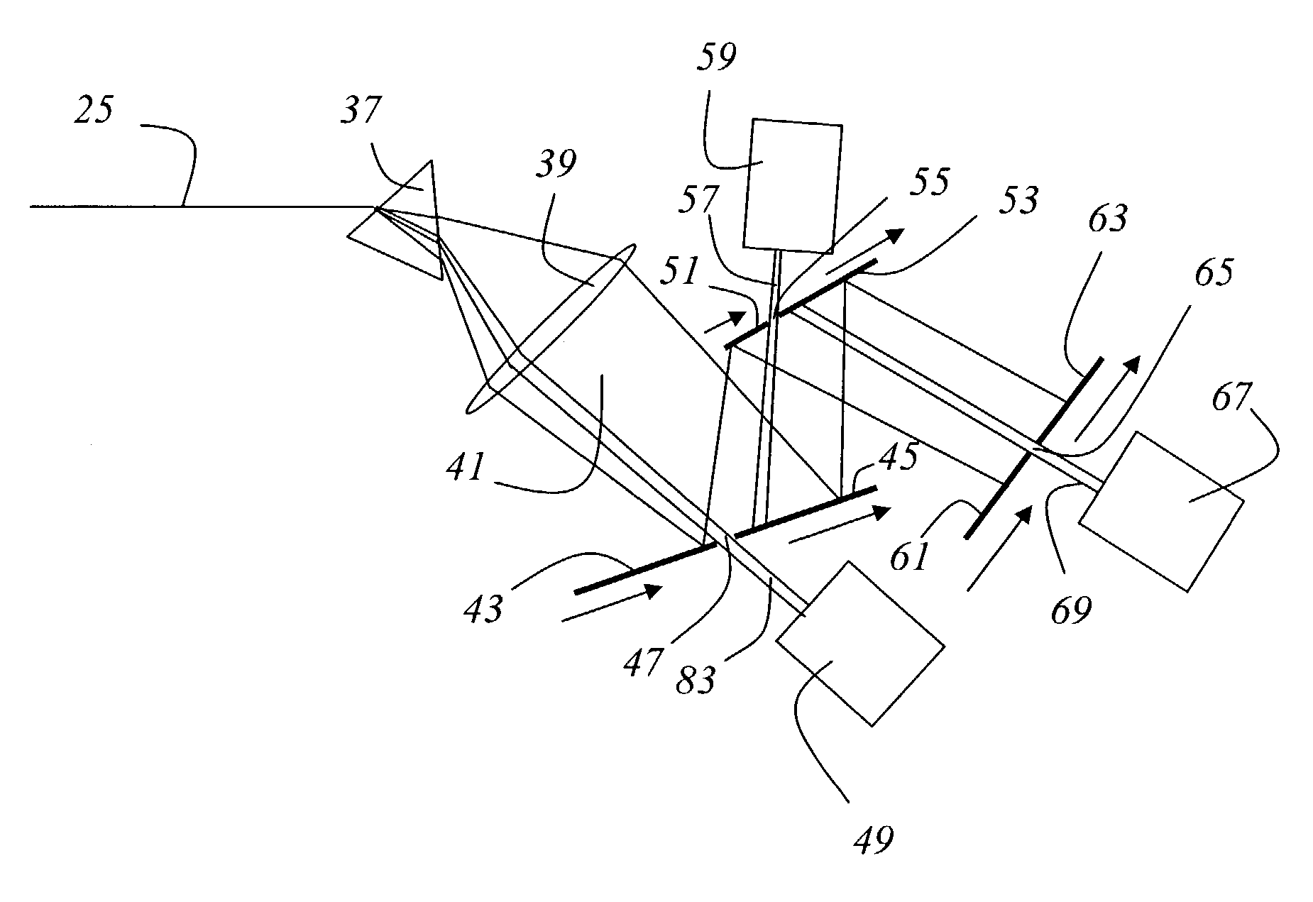
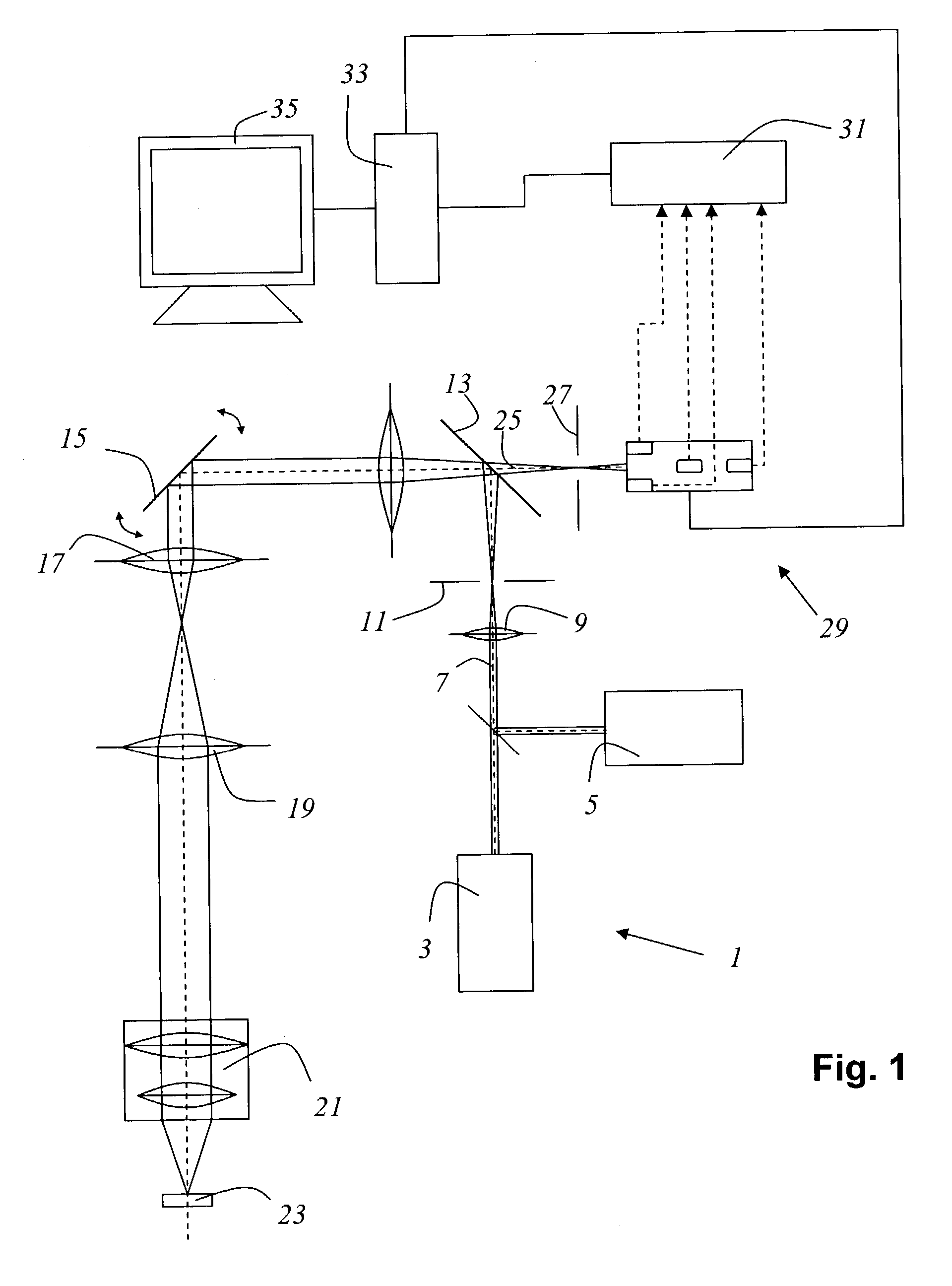
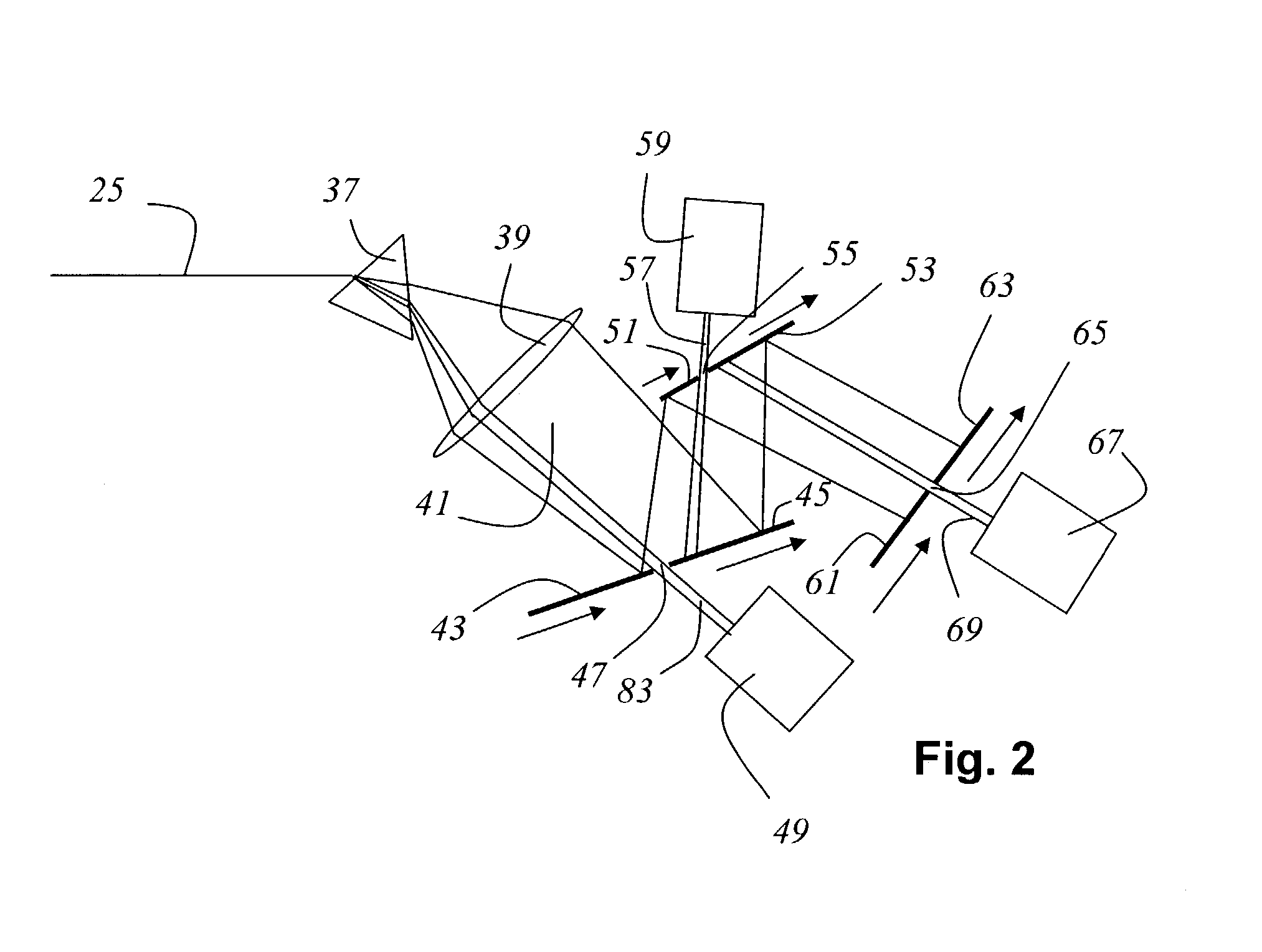
[0041]FIG. 1 schematically shows a scanning microscope according to the present invention that is embodied as a confocal scanning microscope. Illuminating light beam 7, from an illumination system 1 that comprises a first laser 3 and a second laser 5, contains four wavelengths. Illuminating light beam 7 is focused with the aid of optical system 9 onto the illumination pinhole. Illuminating light beam 7 travels via a beam splitter 13 to the gimbal-mounted scanning mirror 15, which guides illuminating light beam 7, through scanning optical system 17, tube optical system 19, and objective 21, over or through specimen 23. With non-transparent specimens 23, illuminating light beam 7 is guided over the specimen surface. With biological specimens 23 (preparations) or transparent specimens, illuminating light beam 7 can also be guided through specimen 23. This means that different focal planes of the specimen can be successively scanned by illuminating light beam 7. Subsequent assembly then...


PUM

PropertyMeasurementUnit
wavelengthaaaaaaaaaa

Abstract

A method for spectral analysis of the light proceeding from a specimen using a multi-band detector comprises the steps of defining an overall spectral region; from the overall spectral region, defining a first spectral subregion and defining at least a second spectral subregion; simultaneously detecting the light proceeding from the specimen in the first and the second spectral subregion, and generating detection values; displacing the first spectral subregion and displacing the second spectral subregion within the overall spectral region; and repeating steps c) and d) until the light has been detected over the entire overall spectral region.

Description

CROSS REFERENCE TO RELATED APPLICATIONS[0001]This application claims priority of the German patent application 102 13 187.2 which is incorporated by reference herein.FIELD OF THE INVENTION[0002]The invention concerns method for spectral analysis of the light proceeding from a specimen using a multi-band detector.[0003]The invention further concerns a scanning microscope having a multi-band detector that detects the light proceeding from a specimen in at least a first and a second spectral subregion.BACKGROUND OF THE INVENTION[0004]Spectral analysis of the light proceeding from a specimen plays a very important role in many fields of specimen examination, in particular in fluorescence microscopy and in confocal scanning microscopy.[0005]In scanning microscopy, a specimen is illuminated with a light beam in order to observe the reflected or fluorescent light emitted from the specimen. The focus of an illuminating light beam is moved in a specimen plane by means of a controllable beam ...

Claims


Application Information

Patent Timeline
Patent Type & Authority Patents(United States)
IPC IPC(8): G01J3/32G01J3/36G01N21/64G02B21/00G02B21/16G02B21/36
CPCG01J3/1256G01J3/32G01J3/36G01N21/6458G02B21/0064G02B21/0076G02B21/008G02B21/16G02B21/365G01N2021/6421
Inventor KNEBEL, WERNER
Owner LEICA MICROSYSTEMS CMS GMBH
Why Eureka
Try Eureka