Method and process for prediction of subsurface fluid and rock pressures in the earth

Inactive Publication Date: 2005-12-20
CONOCOPHILLIPS CO
View PDF11 Cites 112 Cited by
  • Summary
  • Abstract
  • Description
  • Claims
  • Application Information

AI Technical Summary

Benefits of technology

[0088]The technique and software contains a method and ability for creating and applying calibration functions that are controlled by and keyed to specific geologic intervals in the subsurface. These are usually applied to a geologic interval of specific age that is observed to occur across a specific area of the subsurface and has a distinct pore pressure calibration that is different from intervals above and below it in the subsurface. The method and ability allows the user to identify interpreted horizons to which t

Problems solved by technology

In some areas, however, there may be unexpected abnormal increases in pressure, with depth such that mud weight does not compensate pressure; the result can be blowout of the well.
At a number of offshore locations, abnormally high pore pressures have been found even at relatively shallow sub-sea bottom depths (less than about 1500 meters).
The dewatering of clays may result in the formation of relatively impermeable shale layers that slow down the expulsion of water from the u

Method used


Image

  • Method and process for prediction of subsurface fluid and rock pressures in the earth
  • Method and process for prediction of subsurface fluid and rock pressures in the earth
  • Method and process for prediction of subsurface fluid and rock pressures in the earth

Examples


Embodiment Construction

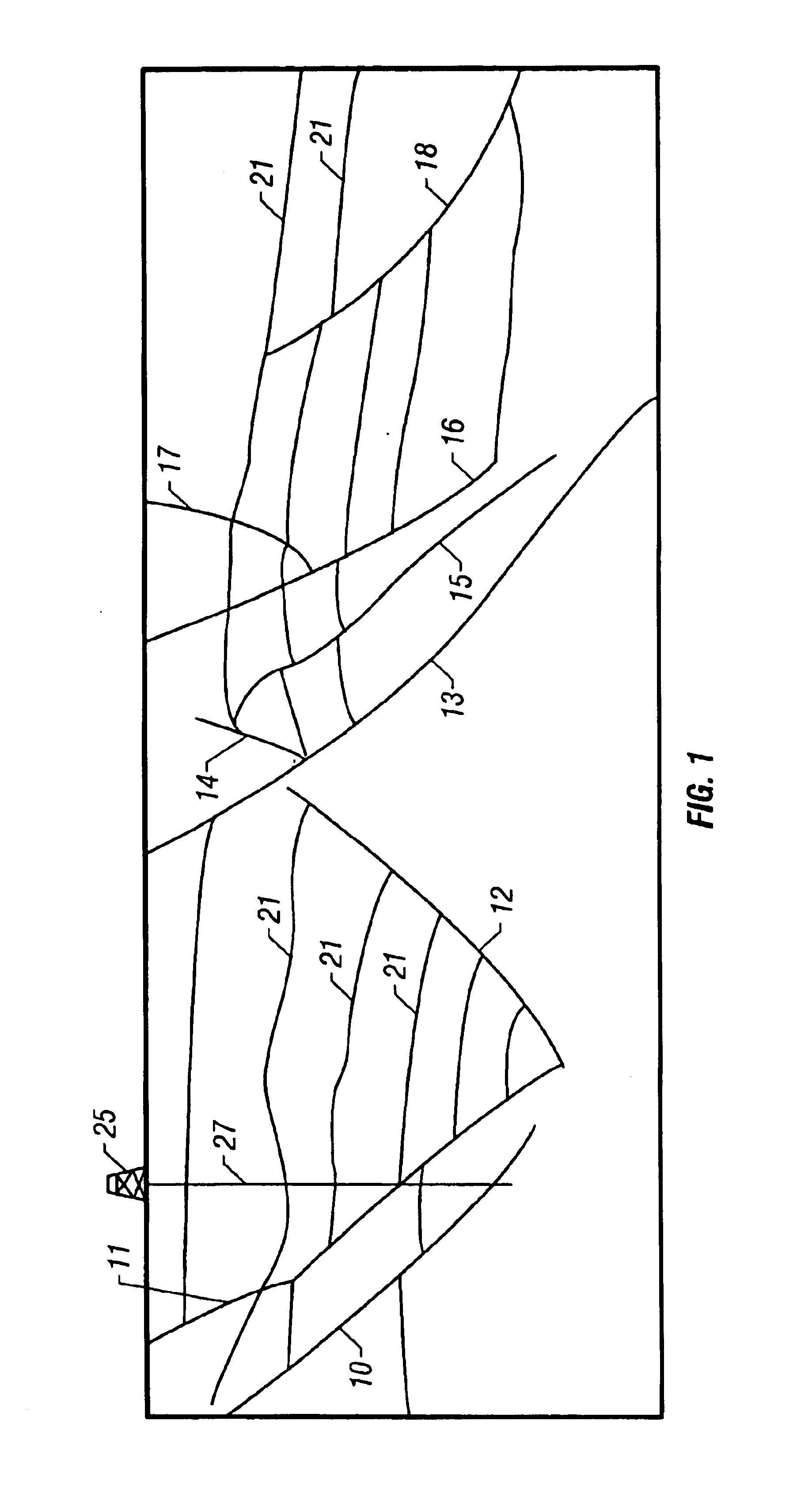
[0119]Referring now to FIG. 1, an example of a vertical section of subsurface region 1 is shown. Indicated in the figure is a well location 25 with a well 27 penetrating the subsurface. A number of faults 10, 11, 12, 13, 14, 15, 16, 17, 18 are indicated in the figure as well as a number of horizons 21 that correspond to geologic intervals of interest.

[0120]In the well 27, a plurality of measurements may be made of the properties of the subsurface formations penetrated by the well. These typically include sonic logs that measure the velocity of compressional and shear velocities, density logs, gamma ray logs that are indicative of the shale content of the formation, and resistivity logs of various types that measure the formation resistivity.

[0121]In addition to these logs, a record is kept of the mud weight that is used for the drilling of the wellbore: as noted above, the mud weight is usually selected to maintain a slightly overbalanced condition wherein the borehole fluid pressur...


PUM


Abstract

A method of determination of fluid pressures in a subsurface region of the earth uses seismic velocities and calibrations relating the seismic velocities to the effective stress on the subsurface sediments. The seismic velocities may be keyed to defined seismic horizons and may be obtained from many methods, including velocity spectra, post-stack inversion, pre-stack inversion, VSP or tomography. Overburden stresses may be obtained from density logs, relations between density and velocity, or from inversion of potential fields data. The seismic data may be P-P, P-S, or S-S data. The calibrations may be predetermined or may be derived from well information including well logs and well pressure measurements. The calibrations may also include the effect of unloading. The determined pressures may be used in the analysis of fluid flow in reservoirs, basin and prospect modeling and in fault integrity analysis.

Description

CROSS-REFERENCES TO RELATED APPLICATIONS[0001]The present application is a divisional of U.S. patent application Ser. No. 10 / 224,793 filed on Aug. 21, 2002, now U.S. Pat. No. 6,751,558, which is a continuation-in-part of U.S. patent application Ser. No. 09 / 805,422 (now U.S. Pat. No. 6,473,696) filed on 13 Mar. 2001. U.S. patent application Ser. No. 09 / 805,422 is related to U.S. patent application Ser. No. 09 / 433,446 (now U.S. Pat. No. 6,694,261) filed on Nov. 4, 1999.BACKGROUND OF THE INVENTION[0002]1. Field of the Invention[0003]The present invention relates generally to geophysical exploration and more particularly to methods for accurately estimating fluid and overburden pressures in the earth's subsurface on local, prospect and basin-wide scales.[0004]2. Background of the Art[0005]During drilling of a borehole, drilling fluids, usually referred to as “mud,” are circulated in the borehole to cool and lubricate the drill bit, flush cuttings from the bottom of the hole, carry cutti...

Claims


Application Information

Patent Timeline
IPC IPC(8): E21BG01V1/28G01V1/30G01V1/32G01V1/34G01V1/38
CPCG01V1/284G01V1/306G01V1/32G01V2210/6248
Inventor HUFFMAN, ALAN R.ONYIA, ERNEST C.LAHANN, RICHARD W.BELL, DAVID W.LANKSTON, ROBERT
Owner CONOCOPHILLIPS CO
Why Eureka
Try Eureka