Self test circuit for evaluating a high-speed serial interface

a serial interface and self-testing technology, applied in the direction of line-transmission details, transmission monitoring, instruments, etc., can solve the problems of affecting the accuracy of the components responsible for transmitting and receiving data, increasing the importance of the test, and affecting the design of known prior art designs

Inactive Publication Date: 2005-12-20
PANASONIC CORP
View PDF6 Cites 32 Cited by
  • Summary
  • Abstract
  • Description
  • Claims
  • Application Information

AI Technical Summary

Benefits of technology

[0009]In an effort to solve the aforementioned needs, it is an object of the present invention to provide a BIST circuit which allows for external data to be input during the self-test operation, and which allows for isolation of the transmitter section and receiver section during the self-test operation.

Problems solved by technology

As the speed of data transmission continually increases, it is becoming increasing important and difficult to accurately test the components responsible for transmitting and receiving the data (i.e., the data transceiver forming the USB interface).
Notwithstanding the ability of known BIST circuits to test transceivers under normal operating conditions, the known prior art designs suffer from the following problems.
First, as the data transmission speeds become faster and faster, the protocols associated with the standards governing the transmission of data are becoming exceedingly complex.
Known BIST circuits do not provide any means for controlling and / or varying the input data during the testing process.
Furthermore, known BIST circuits do not allow for separate control of the transmitter section and the receiver section during the self-test process.

Method used


Image

  • Self test circuit for evaluating a high-speed serial interface
  • Self test circuit for evaluating a high-speed serial interface
  • Self test circuit for evaluating a high-speed serial interface

Examples


Embodiment Construction

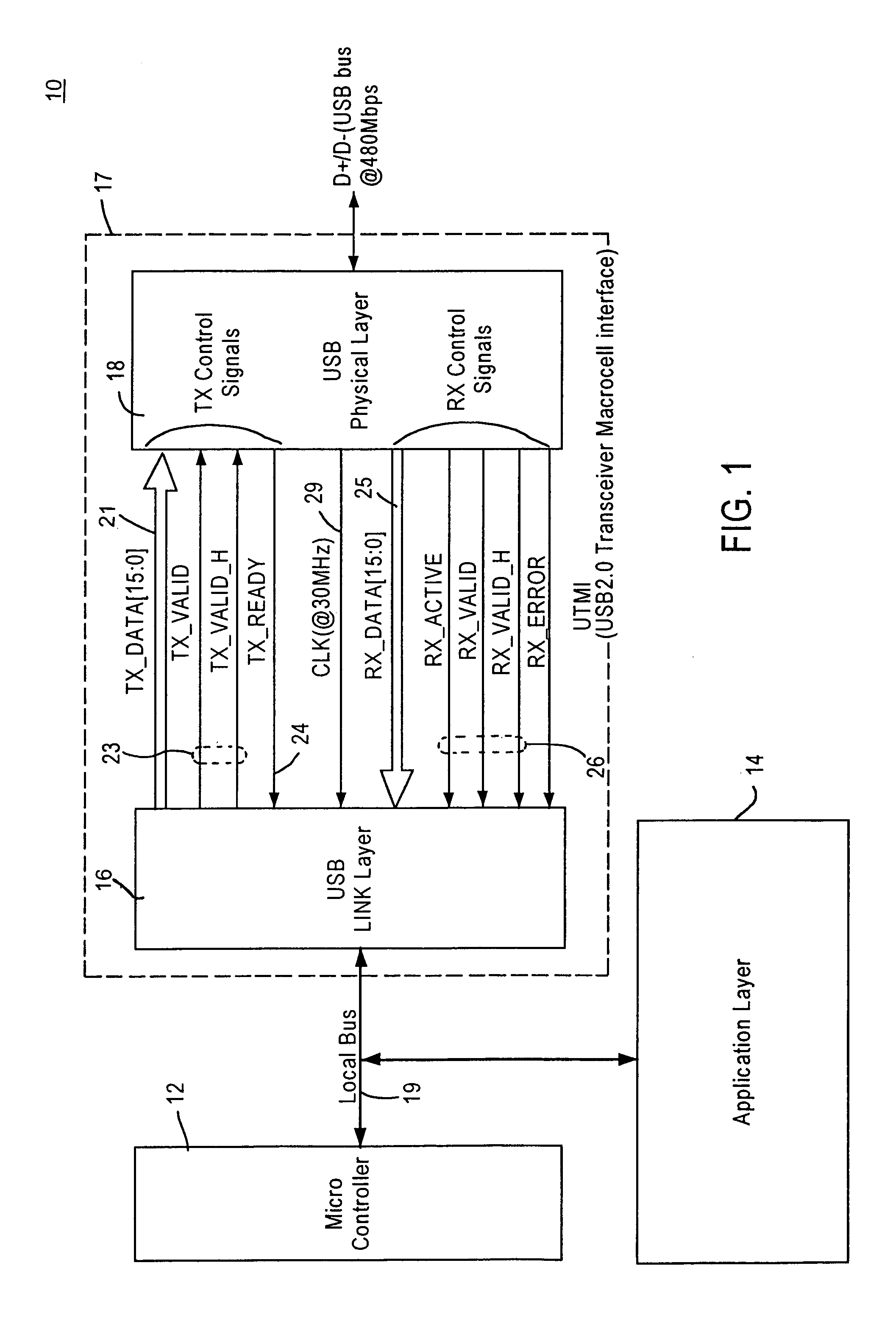
[0020]FIG. 1 illustrates an exemplary block diagram of a peripheral device 10 incorporating a USB serial interface. As shown, the device 10 comprises a microcontroller 12, an application layer 14, a USB link layer 16 and a USB physical layer 18. The microcontroller 12, the application layer 14 and the USB link layer 16 are coupled to one another via a local bus 19. The USB link layer 16 and the USB physical layer 18 are coupled together via signal lines, which are described in detail below.

[0021]In general, the operation of the device 10 is as follows. The microcontroller 12 functions to control the overall operation of the peripheral device 10, including when data will be transmitted by the device 10 via the USB interface 17, which is formed by the USB link layer 16 and the USB physical layer 18. The application layer 14 contains the software associated with the given peripheral device (e.g., CCD camera), which is utilized to program the microcontroller 12. The microcontroller 12 a...


PUM


Abstract

A data transceiver including a self-test data generator for generating test data, which includes a first pseudo-random number generator programmable so as to allow the operator to input the test data values. The data transceiver further includes a transmitter section coupled to the self-test data generator, a receiver section coupled to the transmitter section, and a test data analyzer coupled to the receiver section, wherein the test data analyzer includes a second pseudo-random number generator, which allows the operator to input the data value via a data bus coupled to the test data analyzer. Both the self-test data generator and the test data analyzer are independently controllable.

Description

FIELD OF THE INVENTION[0001]The present invention relates to a method and device for performing self testing of a high-speed serial interface, and more particularly to a built-in test circuit for testing the operation of a high-speed serial interface utilized in the implementation of a universal serial bus (USB) system.BACKGROUND OF THE INVENTION[0002]The use of a Universal Serial Bus (USB) for coupling a peripheral device to a host computer / controller has become well known. Moreover, the maximum transmission rate of the USB is continually increasing. For example, while the USB 1.0 standard provided a transmission rate of 12 Mb / s, the USB 2.0 standard provides for a transmission rate of 480 Mb / s (a full 40×faster). As the speed of data transmission continually increases, it is becoming increasing important and difficult to accurately test the components responsible for transmitting and receiving the data (i.e., the data transceiver forming the USB interface). Moreover, due to the hi...

Claims


Application Information

Patent Timeline
Patent Type & Authority Patents(United States)
IPC IPC(8): H04L1/24
CPCH04L1/24H04L1/244
Inventor TAKINOSAWA, JUN
Owner PANASONIC CORP
Why Eureka
Try Eureka