
Circuits for calculating modular multiplicative inverse

a multiplicative inverse and circuit technology, applied in computation using denominational number representation, instruments, digital transmission, etc., can solve the problem of significant slowing of calculation speed

Inactive Publication Date: 2005-12-20
INTELLECTUAL DISCOVERY INC
View PDF6 Cites 14 Cited by
  • Summary
  • Abstract
  • Description
  • Claims
  • Application Information

AI Technical Summary

Benefits of technology

"The present invention provides a method and circuit for computing a function z(A, B) using a partitioning of the factors into m blocks with k bits in each block. The method involves performing a multiplication and a modulation process using a result register Z0. The initial value of Z0 is set to be equal to the initial value of A and B. The method is carried out using a pipelined circuit with multiple processor elements, which allows for faster and more efficient computation. The invention also includes a method for performing exponentiation modulo N, which is useful in cryptographic applications. The technical effects of the invention include improved speed, efficiency, and security."

Problems solved by technology

However, even though there is a desire for inclusion of a large number of bits in each factor, the speed of calculation becomes significantly slower as the number of digits or bits increase.
However, for real-time cryptographic purposes, speed of encryption and decryption are important concerns.
519–521, Peter L. Montgomery describes an algorithm for “Modular Multiplication without Trial Division.” However, this article describes operations that are impractical to implement in hardware for a large value of N. Furthermore, the method described by Montgomery operates only in a single phase.

Method used


Image

  • Circuits for calculating modular multiplicative inverse
  • Circuits for calculating modular multiplicative inverse
  • Circuits for calculating modular multiplicative inverse

Examples


Embodiment Construction

[0089]The structure and operation of the present invention is dependent upon the partitioning of one of the multiplying factors into a plurality of k bit-wide pieces. Thus, instead of representing a binary number A as

∑i=0n-1⁢ai⁢⁢2i,

one of the multiplying factors in the present invention is represented instead in the form Am-1⁢Rm-1+…+A2⁢R2+A1⁢R+A0=∑j=0m-1⁢Aj⁢Ri,

where R=2k. In this representation, the number A is represented in block form where each of the m blocks includes k bits. That is, each A, represents an integer having k bits.

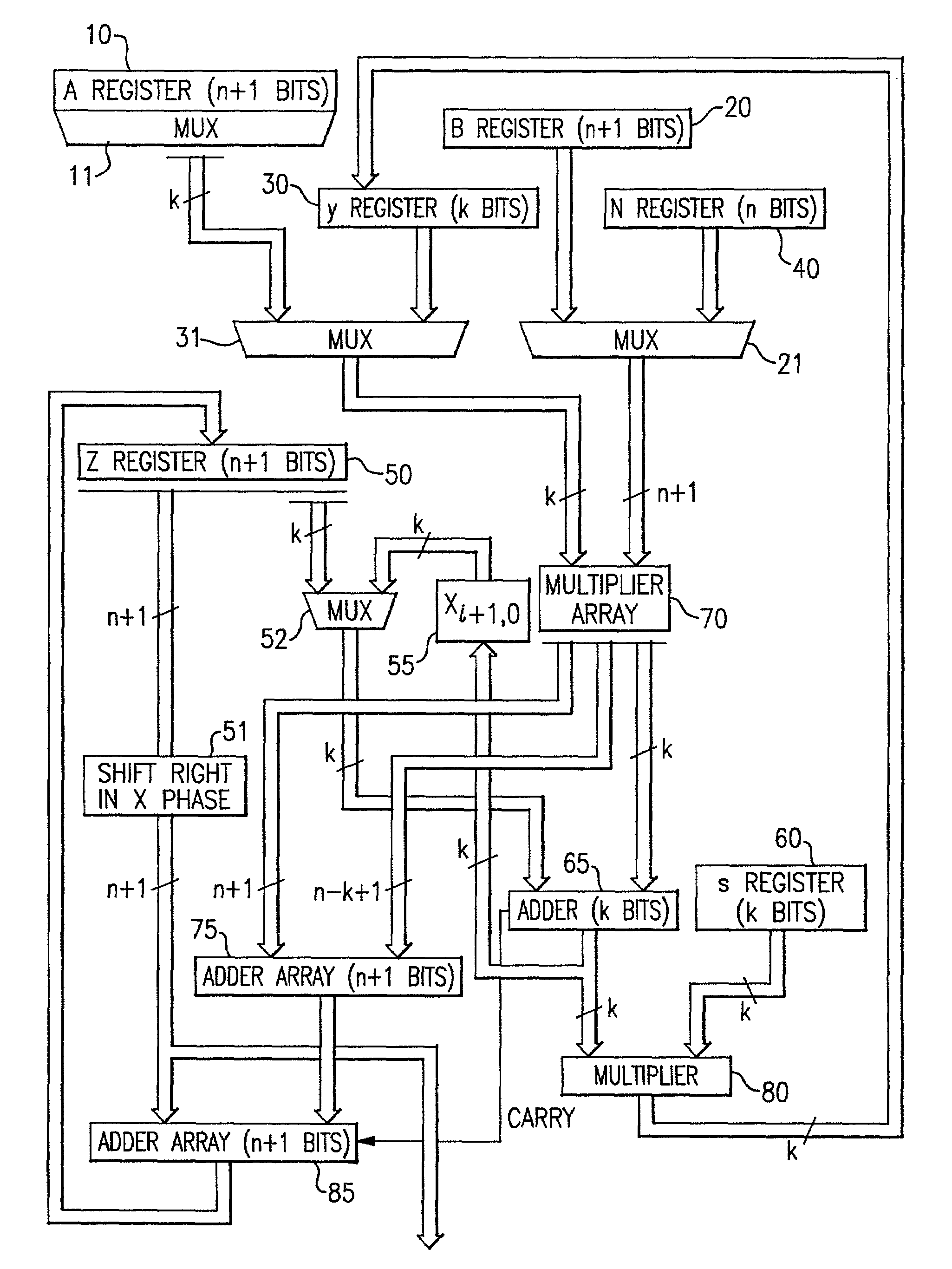
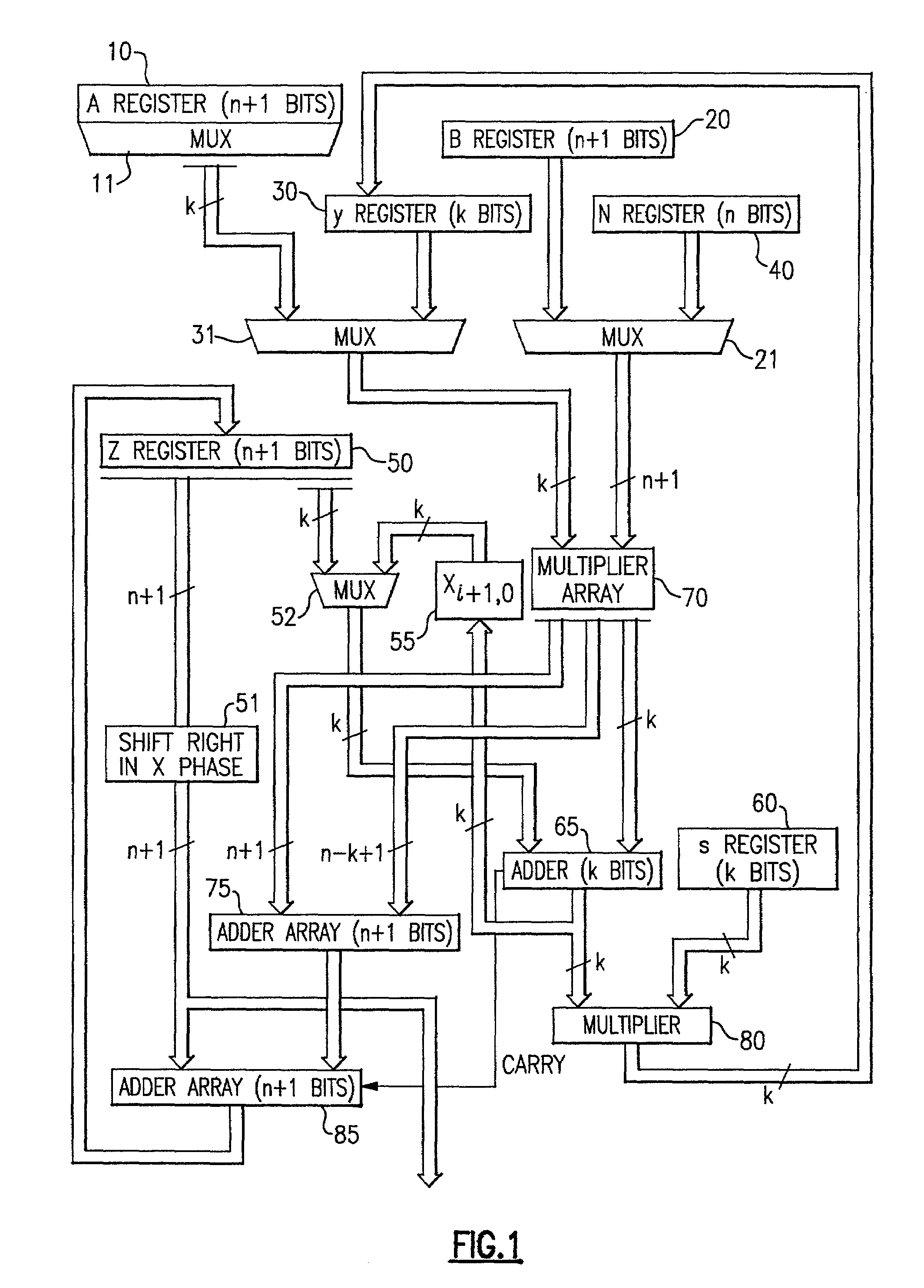
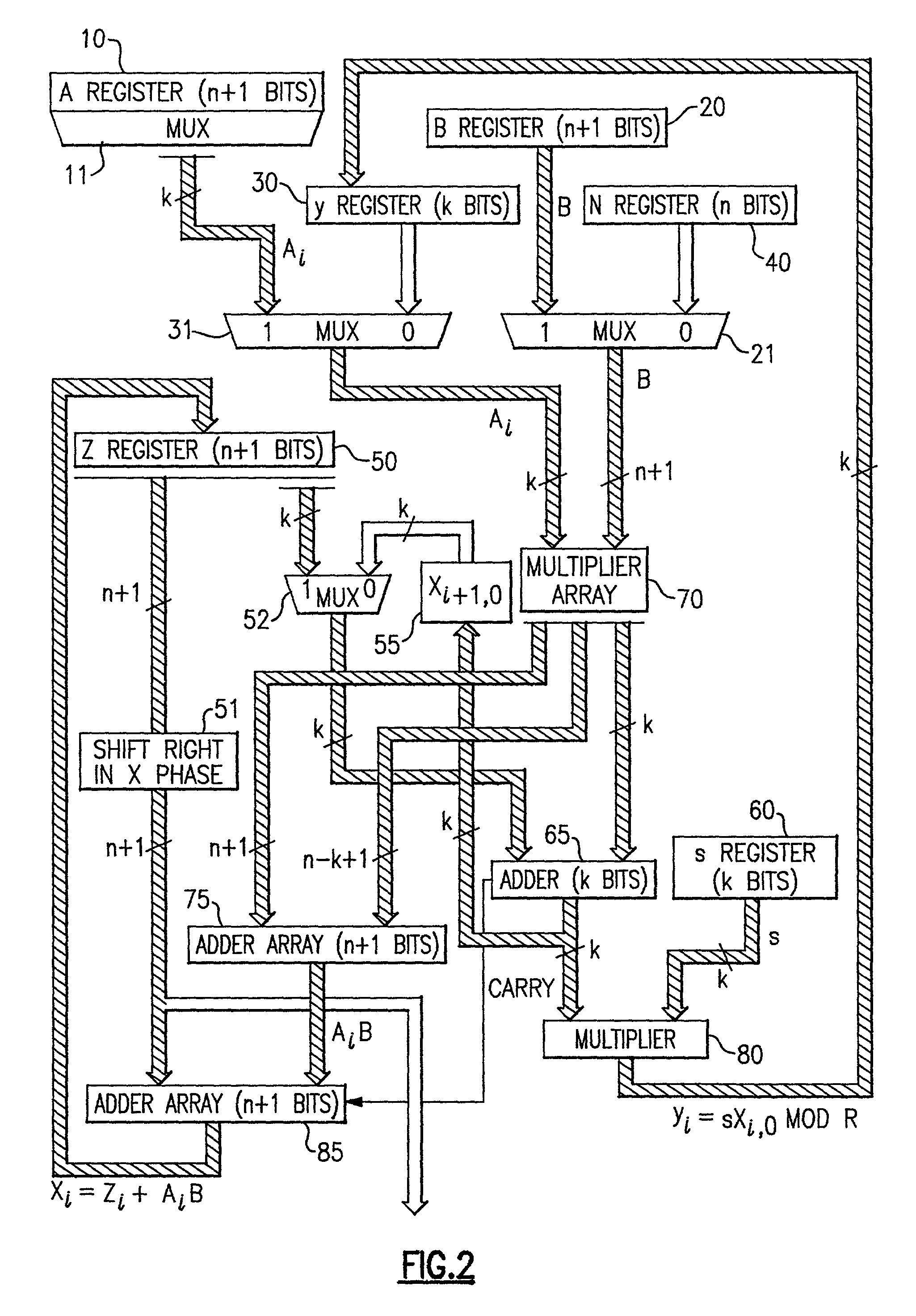
[0090]In the present system, multiplication modulo an odd number N is a significant object. Also, for purposes of understanding the present invention, the symbol n is used to denote the number of bits in the binary representation for N. Also, for present purposes, it is assumed that the number A, as stored in Register A (reference numeral 10 in FIG. 1), is the number that is partitioned into m blocks. In general, the number of blocks m is selected to be t...


PUM


Abstract

The modular exponentiation function used in public key encryption and decryption systems is implemented in a standalone engine having at its core modular multiplication circuits which operate in two phases which share overlapping hardware structures. The partitioning of large arrays in the hardware structure, for multiplication and addition, into smaller structures results in a multiplier design which includes a series of nearly identical processing elements linked together in a chained fashion. As a result of the two-phase operation and the chaining together of partitioned processing elements, the overall structure is operable in a pipelined fashion to improve throughput and speed. The chained processing elements are constructed so as to provide a partitionable chain with separate parts for processing factors of the modulus. In this mode, the system is particularly useful for exploiting characteristics of the Chinese Remainder Theorem to perform rapid exponentiation operations. A checksum mechanism is also provided to insure accurate operation without impacting speed and without significantly increasing complexity. While the present disclosure is directed to a complex system which includes a number of features, the present application is particularly directed to the incorporation and integration of circuits used for calculating a modular multiplicative inverse used as an input parameter to the process.

Description

BACKGROUND OF THE INVENTION[0001]The present application is directed to a method and apparatus for performing encryption and decryption. The application discloses several inventions relating to an overall system for the use of exponentiation modulo N as a mechanism for carrying out the desired cryptological goals and functions in a rapid, efficient, accurate and reliable manner. A first part of the disclosure is related to the construction of a method and its associated apparatus for carrying out modular multiplication. A second part of the disclosure is directed to an improved apparatus for carrying out modular multiplication through the partitioning of the problem into more manageable pieces and thus results in the construction of individual identical (if so desired) Processing Elements. A third part of the disclosure is directed to the utilization of the resulting series of Processing Elements in a pipelined fashion for increased speed and throughput. A fourth part of the disclos...

Claims


Application Information

Patent Timeline
Patent Type & Authority Patents(United States)
IPC IPC(8): G06F7/52G06F7/72H04L9/30
CPCG06F7/723
Inventor CHEN, CHIN-LONGCONDORELLI, VINCENZOFAYAD, CAMIL
Owner INTELLECTUAL DISCOVERY INC
Learn More