Condenser microphone apparatus and its connecting apparatus

a condenser microphone and microphone technology, applied in the direction of transducer details, electrostatic transducer microphones, electrical transducers, etc., can solve the problems of difficult to keep such a frequency low in a wide band, difficult to cope with such a situation, and generate noise, so as to reduce the noise output

Inactive Publication Date: 2005-12-20
PANASONIC CORP
View PDF11 Cites 37 Cited by
  • Summary
  • Abstract
  • Description
  • Claims
  • Application Information

AI Technical Summary

Benefits of technology

[0014]It is an object of the invention to provide a condenser microphone apparatus for reducing a noise output which is generated by a high frequency signal that is radiated or conducted from a transmitting unit of a radio apparatus as mentioned above and to provide a connecting apparatus of such a condenser microphone apparatus.
[0015]To accomplish the above object, according to a preferred aspect of the invention, there is provided a condenser microphone apparatus comprising: a movable electrode which vibrates by an acoustic vibration; a fixed electrode arranged so as to face the movable electrode; amplifying means for buffer-amplifying a voltage across the movable electrode and a voltage across the fixed electrode; a bypass capacitor in which one end is connected to a signal output terminal of the amplifying means and the other end is connected to a common output terminal of the amplifying means; and a series resistor in which one end is connected to the signal output terminal of the amplifying means and the other end is connected to a signal output of the apparatus. With this construction, there are effects such that a noise output due to a high frequency signal which is radiated or conducted from a transmitting unit of a radio apparatus can be reduced in a wide carrier frequency range and, further, a breakdown withstanding voltage of electrostatic discharge which is applied to a microphone signal output terminal can be increased.
[0016]According to another aspect of the invention, there is provided a condenser microphone apparatus comprising: a movable electrode which vibrates by an acoustic vibration; a fixed electrode arranged so as to face the movable electrode; amplifying means for buffer-amplifying a voltage across the movable electrode and a voltage across the fixed electrode; a bypass capacitor in which one end is connected to a signal output terminal of the amplifying means and the other end is connected to the common output terminal of the amplifying means; and a serial circuit of a blocking capacitor and a damping resistor in which one end is connected to the signal output terminal of the amplifying means and the other end is connected to a common output terminal of the amplifying means. With this construction, there is an effect such that a noise output due to a high frequency signal which is radiated or conducted from a transmitting unit of a radio apparatus can be reduced in a wide carrier frequency range.

Problems solved by technology

Hitherto, the condenser microphone apparatus has a problem such that when it is used in a cellular phone or the like, noises are generated due to radiation of a high frequency signal from a transmitting unit.
As mentioned above, since a magnitude of the high frequency voltage that is applied to the drain of the FET 19 is largely changed depending on the frequency of the high frequency signal, it is difficult to keep such a frequency low in a wide band.
Therefore, it is impossible to cope with such a situation merely by the bypass capacitor as a conventional countermeasure.

Method used


Image

  • Condenser microphone apparatus and its connecting apparatus
  • Condenser microphone apparatus and its connecting apparatus
  • Condenser microphone apparatus and its connecting apparatus

Examples


first embodiment

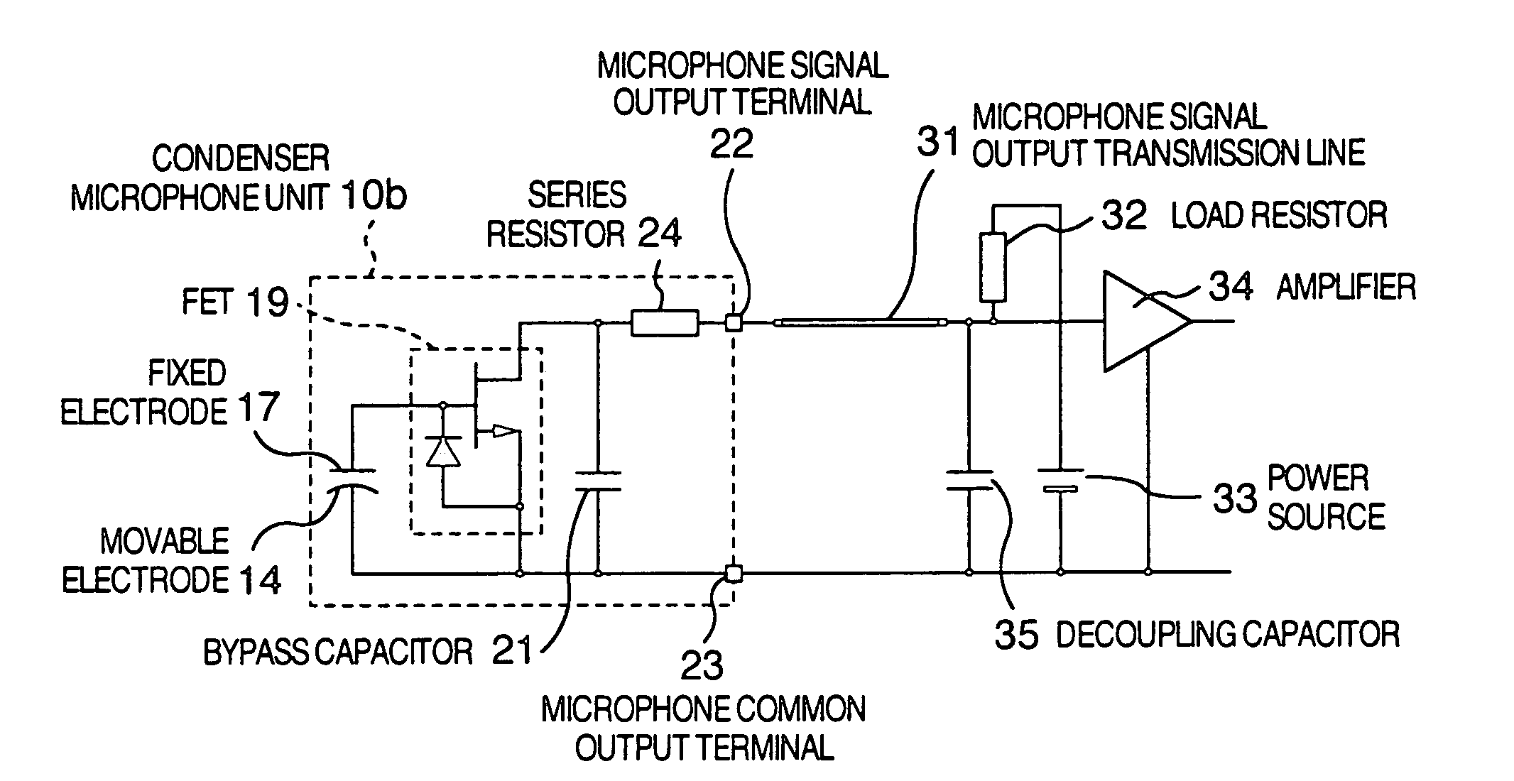
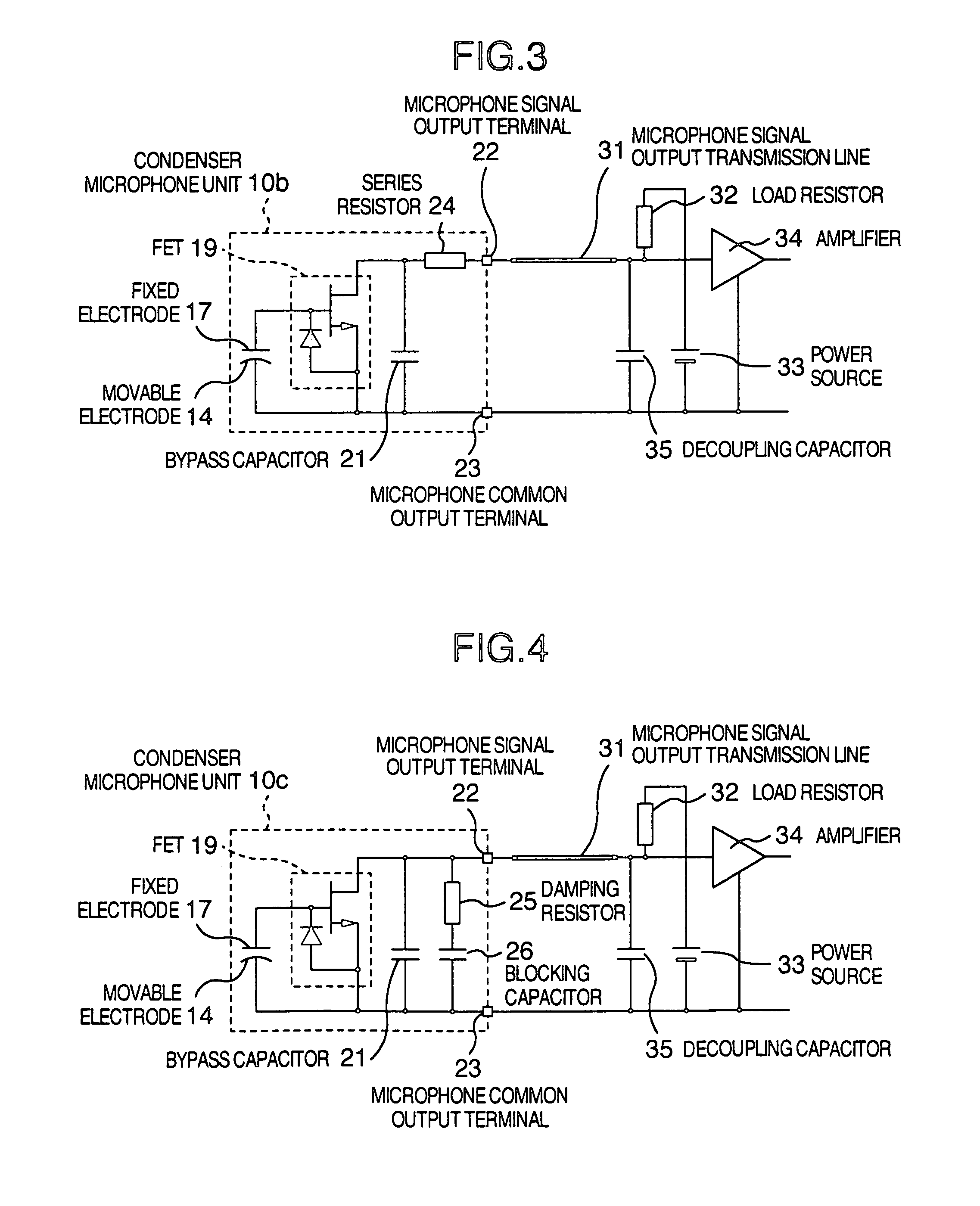
[0036]FIG. 3 is a circuit diagram of a condenser microphone apparatus in the first embodiment of the invention. FIG. 3 differs from the circuit diagram of the conventional condenser microphone apparatus shown in FIG. 2 with respect to a point that a series resistor 24 is added. In a condenser microphone unit 10b shown in FIG. 3, the series resistor 24 is inserted to an interval between the drain of the FET 19 and the microphone signal output terminal 22.

[0037]The series resistor 24 is provided to limit a resonance current and arranged in series with a series resonance circuit comprising the microphone signal output transmission line 31 and bypass capacitor 21 in terms of an equivalent circuit of a high frequency. Since an effective series resistance of the bypass capacitor 21 is equal to or less than 1Ω, by setting a resistance of the series resistor 24 to a value within a range from tens of Ω to hundreds of Ω, a resonance current of the microphone signal output transmission line 31...

second embodiment

[0039]FIG. 4 is a circuit diagram of a condenser microphone apparatus in the second embodiment of the invention. FIG. 4 differs from the circuit diagram of the conventional condenser microphone apparatus shown in FIG. 2 with respect to a point that a damping resistor 25 and a blocking capacitor 26 are added. In a condenser microphone unit 10c shown in FIG. 4, the damping resistor 25 and the blocking capacitor 26 for blocking a direct current are serially connected and such a serial circuit is connected in parallel with the drain and source of the FET 19. The damping resistor 25 and blocking capacitor 26 are provided to damp a parallel resonance and arranged in parallel with the parallel resonance circuit comprising the microphone signal output transmission line 31 and bypass capacitor 21 in terms of an equivalent circuit of a high frequency. Since an effective series resistance of the bypass capacitor 21 is equal to or less than 1Ω, an impedance at the time of a parallel resonance o...

third embodiment

[0041]FIG. 5 is a circuit diagram of a conventional condenser microphone unit and a connecting apparatus (connector) in the third embodiment of the invention. In FIG. 5, series resistor 27 is included in a connecting apparatus 40a. Both ends of the series resistor 27 are connected to a connector signal input terminal 41 and a connector signal output terminal 43. The microphone signal output terminal 22 and microphone common output terminal 23 of a condenser microphone unit 10a are connected to the connector signal input terminal 41 and a connector common input terminal 42, respectively. The connector signal output terminal 43 and a connector common output terminal 44 are connected to the microphone signal output transmission line 31 and a common terminal (ground) on a mother board of an apparatus such as a cellular phone or the like, respectively, and construct a condenser microphone apparatus for converting an acoustic signal of the cellular phone or the like into an electric signa...


PUM


Abstract

A condenser microphone apparatus which is used for a radio apparatus in order to reduce noises generated due to radiation of a high frequency signal of a transmitting unit. A series resistor is provided between a bypass capacitor provided between a drain and a source of an FET and a microphone signal output transmission line in order to prevent a high frequency voltage from being increased due to a resonance of the bypass capacitor and microphone signal output transmission line. Thus, the noises due to the radiation of the high frequency signal can be reduced.

Description

BACKGROUND OF THE INVENTION[0001]1. Field of the Invention[0002]The invention relates to a condenser micro-phone apparatus for converting an acoustic vibration into an electric signal and, more particularly, to such an apparatus having an impedance converting device therein.[0003]2. Description of the Related Art[0004]Generally, a condenser microphone apparatus comprises a condenser microphone unit, a microphone signal output transmission line, a load resistor, a power source, and the like.[0005]Hitherto, the condenser microphone apparatus has a problem such that when it is used in a cellular phone or the like, noises are generated due to radiation of a high frequency signal from a transmitting unit. For a countermeasure against such a problem, as a condenser microphone apparatus, a method whereby a bypass capacitor is provided between a source and a drain of an internal FET (field effect transistor) has been known.[0006]First, a construction of a condenser microphone unit in the co...

Claims


Application Information

Patent Timeline
Patent Type & Authority Patents(United States)
IPC IPC(8): H04R19/04
CPCH04R3/007H04R19/04
Inventor IKEDA, MASAHARU
Owner PANASONIC CORP
Why Eureka
Try Eureka