Diverter valve

a valve and diverter technology, applied in the field of valve structures, can solve the problems of limited pressure range operation, tendency for knocking, leakage, etc., and achieve the effect of reducing the restriction effect of the flow regulator on the flow

Inactive Publication Date: 2005-12-27
TCL MFG
View PDF13 Cites 45 Cited by
  • Summary
  • Abstract
  • Description
  • Claims
  • Application Information

AI Technical Summary

Benefits of technology

[0006]The present invention provides a diverter valve, comprising a housing having an inlet, a first outlet, and a second outlet, a valve element mounted in said housing, movable between a closed position and an open position with respect to the first outlet, a piston means for moving said valve element, with said piston means being responsive to pressure differential between said second outlet and said inlet such tha...

Problems solved by technology

However, a problem with existing diverter valves is that they only operate over a limited pressure range.
At high pressures, leakage tends to occur.
At low pressures, there is not enough...

Method used


Image

  • Diverter valve
  • Diverter valve
  • Diverter valve

Examples


first embodiment

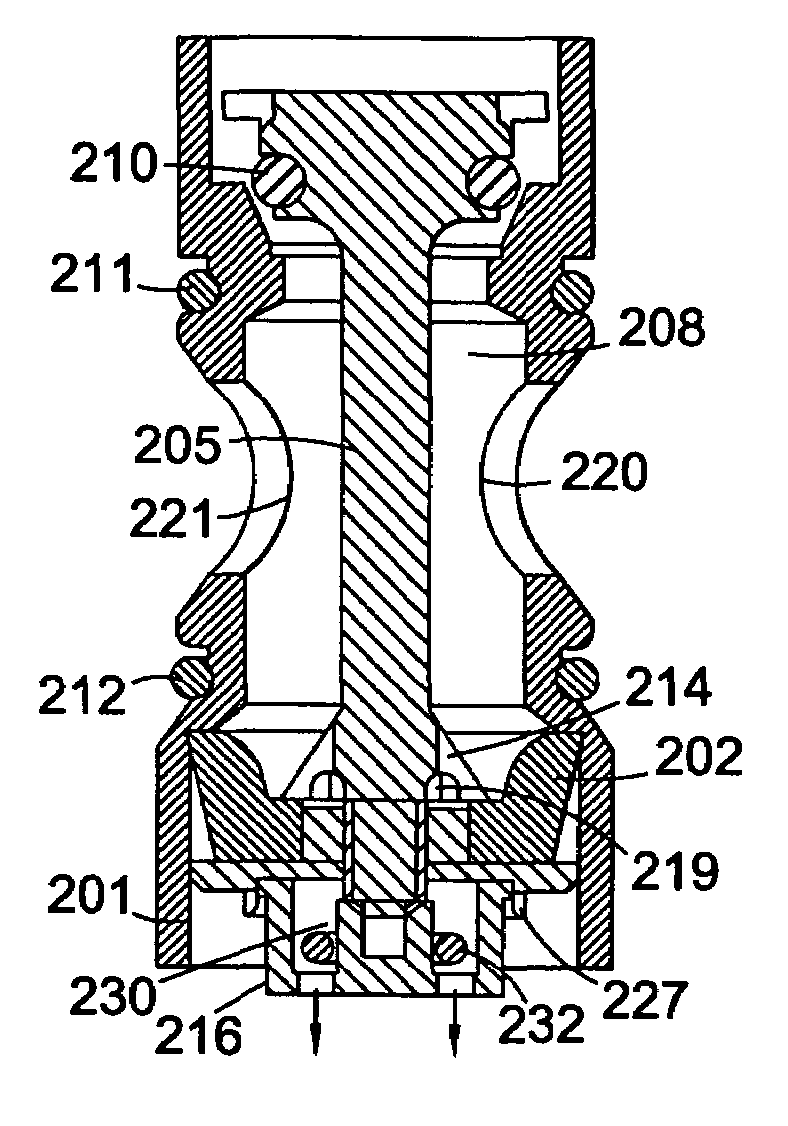
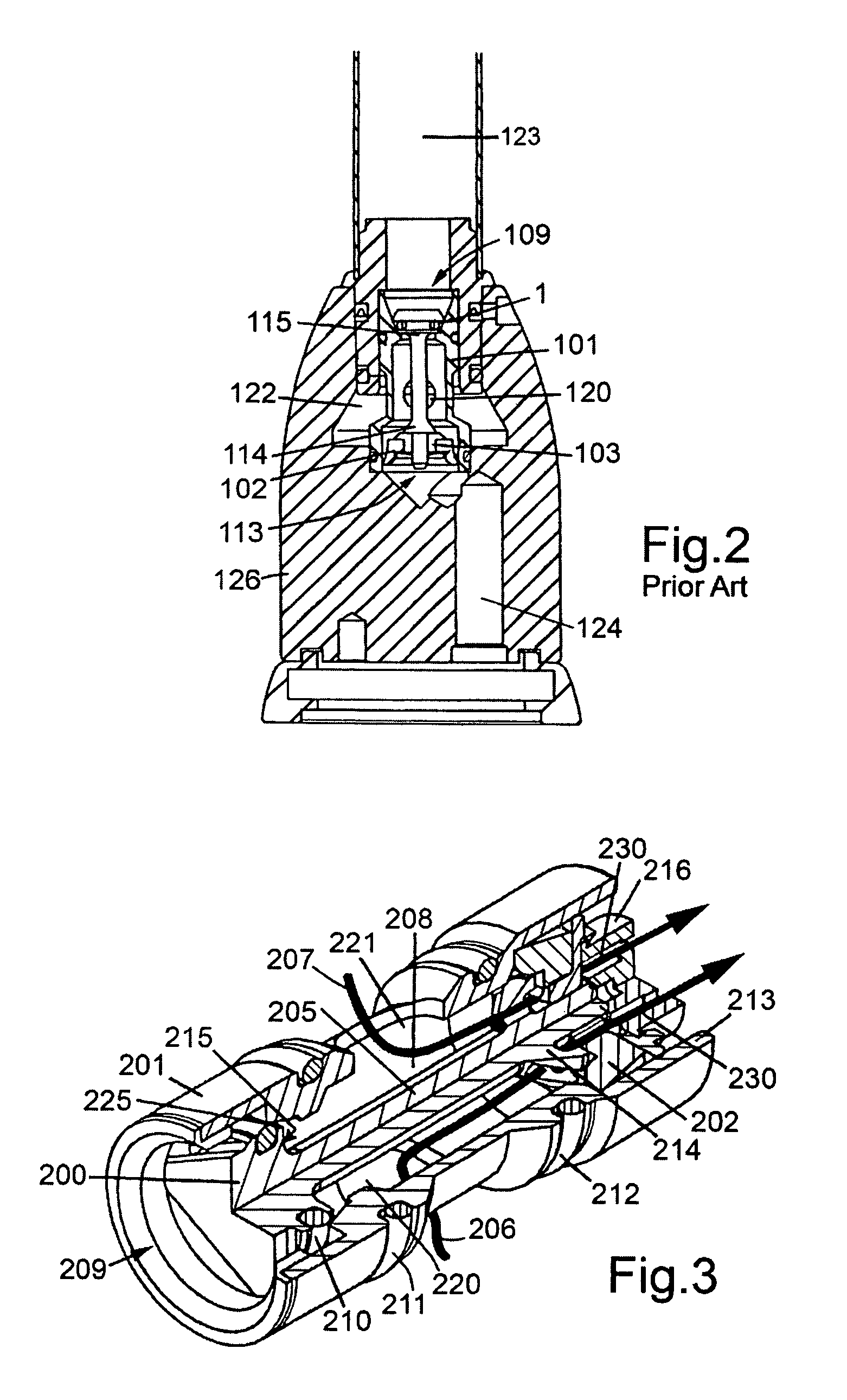
[0034]FIG. 3 shows a valve according to the invention. The arrangement is generally similar to the arrangement of FIGS. 1 and 2. The rubber cup washer 202 has been inverted to trap the water and form a seal between the outer lip of the washer 202 and the housing 201. Again, the rubber cup washer 202 and the lower piston element 214 together form a lower piston, with larger effective cross section than the top piston 215. The valve has a central waterway comprising several channels 219 through which the flow of water is routed to a standard flow regulator 216 that restricts the flow to a substantially constant rate over a range of water pressure. This results in an increase in pressure in the pressure chamber 208, producing a much improved seal on the nozzle. The valve of the invention works between 1 bar and 10 bar. An additional beneficial effect is that the pressure of the water pushes and locks the cup washer 202 against the inside of the housing 201, reducing the tendency for th...

second embodiment

[0041]FIGS. 7 to 18 show the invention, in which the valve housing is integrated with the spout of the faucet. As shown in FIG. 7, the valve assembly comprises an outer housing 301 which is attached to the inlet end 370 of the spout 371. In this embodiment, the outer housing 301 is soldered to the spout with a solder ring placed in a groove in the outer housing 301. The solder joint is concealed by a decorative ring held in place by an O-ring.

[0042]An upper valve housing part 845 is inserted into the outer housing 301, and sealed against it using an O-ring. A guide plate 346 and seating O-ring 347 are fitted into a channel 365 (FIG. 9) in the upper valve housing 345. The end of the valve member 300 is fastened to the guide plate 346. A flow regulator 316, of similar design to the flow regulator 216 of the first embodiment, is positioned against the lower part of the valve member 300. The lower part of the outer housing 301, containing the valve assembly, is fixed in position inside ...


PUM


Abstract

A diverter valve comprises a housing having inlets, a first outlet, and a second outlet. The inlets are connected to hot and cold water supplies, and mixing of the hot and cold water occurs both inside the housing and inside a mixing chamber external to the valve. The first outlet is connected to a spout, and the second outlet is connected to a spray unit. A valve element is mounted in the housing, movable between a closed position and an open position with respect to the first outlet. A piston member comprising a first piston at the bottom end of the valve element, and a second smaller piston at the top end of the valve is responsive to pressure differential between the second outlet and the inlet for movement to a first and second position. When a lower pressure exists at the second outlet, the piston member moves to the second position, closing off the first outlet. The valve also includes a flow regulator to regulate the flow through the second outlet. Fluid is directed into the flow regulator by channels running through the bottom piston. The flow regulator allows pressure to build up inside the valve, providing an increased closure force on the second outlet when the first outlet is open. An inverted cup washer prevents fluid leakage from the second exit by any other route than through the flow regulator. Build up of water inside this cup washer pushes it against the housing, providing an anti-knocking mechanism. The diverter valve may be included in a faucet assembly along with a separate isolated channel for filtered water.

Description

INTRODUCTION AND BACKGROUND[0001]This invention relates to valve structures and more particularly to a diverter valve that incorporates an improved closure mechanism and anti-knocking mechanism.[0002]Diverter valves are commonly used in water tap or faucet assemblies to divert water between a spout and a hand spray. When the spray is operated, the diverter valve shuts off the flow of water to the spout. When the spray is shut off, the diverter valve automatically adjusts to allow water to flow from the spout again. Such systems are particularly used in domestic environments, as well as commercial establishments,[0003]A common method of implementing this automatic diverter system is by means of a piston mechanism. The valve comprises a housing containing a valve member shaped to act as a piston. The valve member is movable from a first position, in which the outlet to the spout is open, to a second position, in which the outlet to the spout is closed off. The piston is responsive to ...

Claims


Application Information

Patent Timeline
IPC IPC(8): F16K11/048
CPCF16K11/048Y10T137/2521Y10T137/2683Y10T137/794Y10T137/87153
Inventor PERRIN, ROBERT BRIAN
Owner TCL MFG
Why Eureka
Try Eureka