PWM voltage clamp for driver circuit of an electric fluid dispensing gun and method

a technology of electric fluid and driver circuit, which is applied in the direction of valves, relays, mechanical devices, etc., can solve the problems of reducing line voltage, affecting the adhesive deposition process, and dispense too soon, so as to improve performance, improve quality, and improve the effect of quality

Inactive Publication Date: 2005-12-27
NORDSON CORP
View PDF12 Cites 9 Cited by
  • Summary
  • Abstract
  • Description
  • Claims
  • Application Information

AI Technical Summary

Benefits of technology

[0010]The present invention provides an unregulated gun driver for a fluid dispenser that has an improved performance. The gun driver of the present invention executes a stable, consistent and high quality fluid dispensing process independent of line voltage variations. Further, the gun driver of the present invention has the advantages of being less expensive, operating more efficiently with less power loss and requiring less cooling than regulated gun drivers. In addition, the unregulated gun driver of the present invention can be readily added to many existing gun driver circuits. Thus, the fluid dispenser of the present invention is especially advantageous in those applications where better performance is required at a lesser cost.
[0011]In accordance with the principles of the present invention and the described embodiments, the invention in one embodiment provides an electric fluid dispenser for dispensing a fluid onto a substrate. The dispenser has a dispensing valve movable between open and closed positions for controlling a flow of the fluid from said fluid dispenser. The dispenser further has a source of power providing a nonconstant voltage to a power switching circuit. A solenoid is connected to the power switching circuit and is capable of causing the dispensing valve to move between the open and closed positions. A control circuit is responsive to the nonconstant voltage and provides a drive signal having a time variable component determined by the nonconstant voltage from the source of power. The power switching circuit, in response to the control signal, provides an output signal to the solenoid causing said dispensing valve to move between the open and closed positions substantially independent of variations in the nonconstant voltage.

Problems solved by technology

Uncontrolled and unpredictable variations in the actuation time of the dispensing gun adversely impact the adhesive deposition process.
If adhesive is to be dispensed on a package flap moving past the dispensing gun, an increase in line voltage causing the gun to switch-on or open faster than expected may cause adhesive to be dispensed too soon.
Opening the gun too soon may cause adhesive to be dispensed prior to a leading edge of the flap reaching the dispensing location.
Similarly, a decrease in line voltage causes the gun to switch-off or close slower than expected.
This slower gun operation may cause adhesive to continue to be dispensed after a trailing edge of the flap passes the dispensing location.
Any unpredicted dispensing of adhesive onto a surface not intended to receive adhesive, potentially results in a scrap product.
In addition, spurious adhesive spray that misses the substrate may lead to additional, time consuming, labor intensive and expensive cleaning and maintenance of equipment and areas adjacent the adhesive dispensing gun.
Thus, such line voltage variations may result in a less efficient, less economical and / or lower quality fluid dispensing operation.
However, regulated gun drivers are more expensive than unregulated gun drivers and create more heat which requires more cooling and thus, further adds to their cost.

Method used


Image

  • PWM voltage clamp for driver circuit of an electric fluid dispensing gun and method
  • PWM voltage clamp for driver circuit of an electric fluid dispensing gun and method
  • PWM voltage clamp for driver circuit of an electric fluid dispensing gun and method

Examples


Embodiment Construction

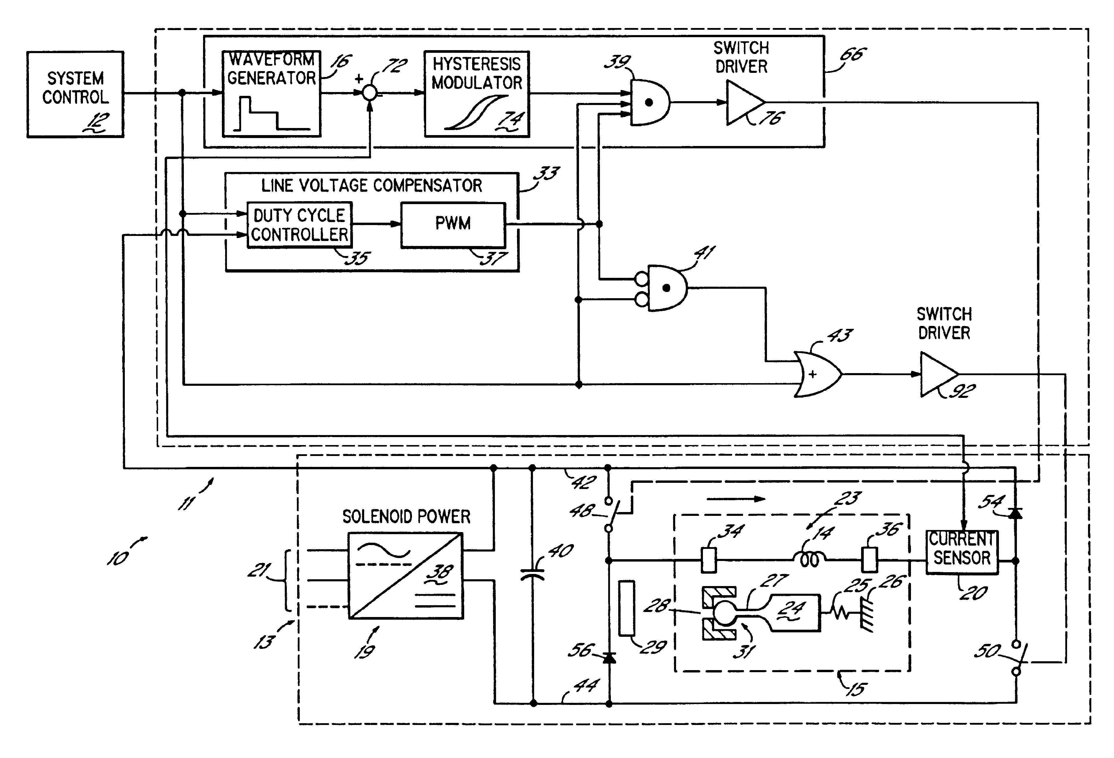
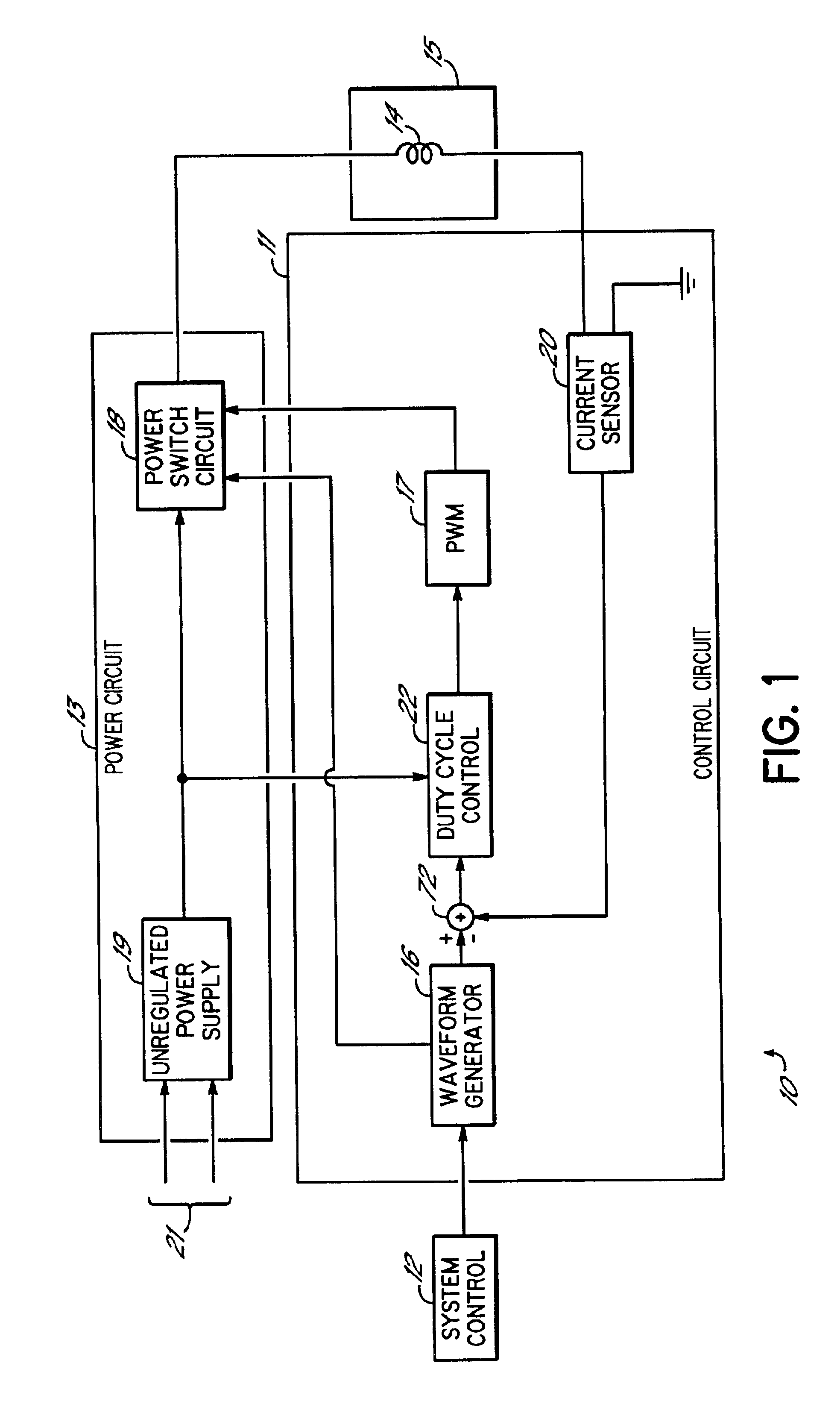
[0020]FIG. 1 illustrates an unregulated gun driver or controller 10 for an electric fluid dispensing gun normally used to dispense adhesive onto a substrate moving with respect to the gun. As previously discussed, electric guns are preferred because of the precision with which they may be controlled during a fluid dispensing operation. The gun driver 10 has a control circuit 11 operating in response to signals from a system control 12 to provide a stepped waveform to a power circuit 13. The system control 12 includes all of the other known dispensing system or machine controls necessary for the operation of the dispensing system, for example, a pattern control. The system control 12 also includes input devices such as a keypad, pushbuttons, etc. and output devices such as a display, indicator lights, etc. that provide communication links with a user in a known manner. Within the power circuit 13, a power switch circuit 18 is connected to an unregulated power supply 19 and provides a...


PUM


Abstract

An electric fluid dispenser for dispensing a fluid onto a substrate. A power switching circuit is connected to an unregulated power supply providing a varying voltage. A solenoid connected to the power switching circuit operates a dispensing valve to move between open and closed positions. A control circuit is responsive to the varying voltage from the power supply and provides a drive signal to the power switching circuit having a time variable component determined by the varying voltage. The power switching circuit, in response to the drive signal, provides an output signal to the solenoid that causes the dispensing valve to move between the open and closed positions substantially independent of the varying voltage from the unregulated power supply.

Description

[0001]This application claims the benefit of U.S. Provisional Application No. 60 / 244,512 entitled, “PWM Voltage Clamp for Driver Circuit of an Electric Dispensing Gun and Method”, filed on Oct. 31, 2000.FIELD OF THE INVENTION[0002]The present invention relates generally to fluid dispensing systems for dispensing flowable material, such as adhesives, sealants, caulks and the like, onto a substrate and, more particularly, to a driver circuit for controlling an operation of a solenoid-actuated valve within an electric dispensing gun.BACKGROUND OF THE INVENTION[0003]Electric fluid dispensers have been developed for dispensing applications requiring a precise placement of a fluid, for example, an adhesive, onto a moving substrate, for example, packaging or a woven product. Dispensing guns of this type include a liquid passage that communicates between a pressurized adhesive supply and a valve mechanism provided at the end of the liquid passage. The valve mechanism is typically a movable ...

Claims


Application Information

Patent Timeline
Patent Type & Authority Patents(United States)
IPC IPC(8): B05C11/10F16K31/06
CPCF16K31/0675B05C11/1026
Inventor NEAR, TIMOTHY P.
Owner NORDSON CORP
Why Eureka
Try Eureka