
Plating of brazed RF connectors for T/R modules

a technology of rf connector and t/r module, which is applied in the direction of coupling contact member, coupling device connection, coupling device two-part coupling device, etc., can solve the problems of pins not having proper plating, large number of packages rejected, and catastrophic failure of the entire t/r module package, so as to improve the plating flow of plating material and facilitate conta

Inactive Publication Date: 2005-12-27
NORTHROP GRUMMAN SYST CORP
View PDF11 Cites 6 Cited by
  • Summary
  • Abstract
  • Description
  • Claims
  • Application Information

AI Technical Summary

Benefits of technology

[0008]It is another object of the present invention to improve the plating flow of plating material throughout the interior of an RF connector for a T / R module package during fabrication of a T / R module.
[0009]It is a further object of the present invention to provide a plating process wherein the plating fluid is made to more easily contact and flow around all of the interior metallized surfaces of an RF connector shroud.
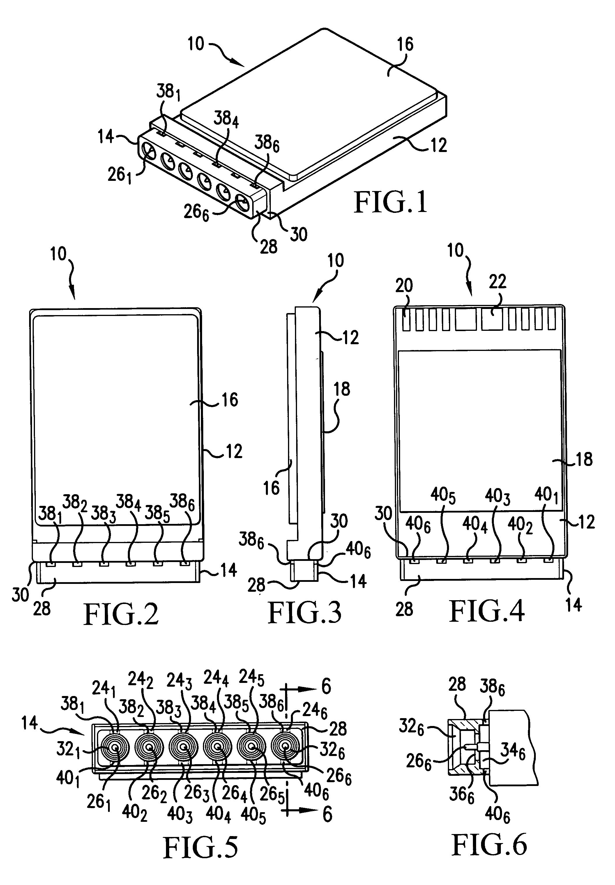
[0010]These and other objects are achieved by initially providing openings such as slots or holes in the shroud of an RF connector of a T / R module package in the region of the connector pins prior to being brazed to a ceramic substrate so as to subsequently allow plating solution to flow freely throughout the interior of the RF connector and particularly around the connector pins. The slots or holes are large enough to allow proper plating of the interior of the connector but small enough to prevent any radiation through the connector to the exterior of the T / R module package.

Problems solved by technology

The materials involved in this operation, Kovar for the center pin and shroud and Cusil brazing material, are prone to corrosion and therefore require gold plating to prevent corrosion in any non-hermetic environment.
Any non-plated area on the center pin area can result in corrosion of the center pin and loss of the RF signal, resulting in a catastrophic failure of the entire T / R module package.
It has been found that due to the lack of good plating solution flow throughout the interior of the RF connector, a relatively large number of packages have been rejected because of unplated areas around the connector center pins.
The pins do not have proper plating, for example, where the pin is brazed to the ceramic package.
This plating deficiency occurs as a result of a lack of flow of the plating solution within the connector.
Since plating is performed at the end of the package fabrication process, a rejection of the package results in a loss at the most expensive point in the process of a finished product.
Thus an unreasonable number of failures in a production system using this type of RF interconnect can result in a relatively large increase in the overall cost of acceptable or “good” T / R module packages.

Method used


Image

  • Plating of brazed RF connectors for T/R modules
  • Plating of brazed RF connectors for T/R modules

Examples


Embodiment Construction

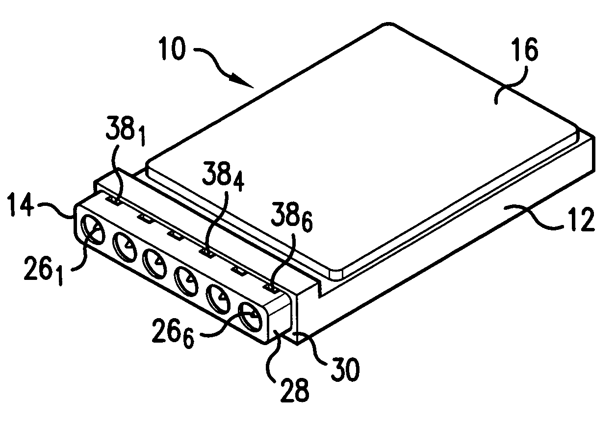
[0019]Referring now collectively to the drawings and more particularly to FIGS. 1–4, shown is a microwave transmit / receive (T / R) module 10 utilized in connection with an active electronically scanned array. The details of such a T / R module is shown and described in the above-referenced U.S. Pat. No. 6,114,986. What is common between the T / R module 10 of the subject invention and that shown and described in U.S. Pat. No. 6,114,986, is the use of a dielectric substrate 12 onto which an RF connector assembly 14 is brazed. The substrate 12 constitutes a multi-level configuration of high temperature co-fired ceramic (HTCC) in which active and passive circuit elements, not shown, are located to provide routing of RF signals between respective antenna elements of the array and the circuit elements as well applying DC power supply voltages. To protect the interior of the substrate 12, a cover plate 16 is secured to the top of the substrate. A heat sink plate 18 is also provided on the botto...


PUM


Abstract

Slots or apertures are formed in the connector shroud of a T / R module in a plane perpendicular to the axis of the connector so as to allow plating solution to flow freely through the entire inner portion of the connector, particularly the rear portion, during fabrication of the T / R module. The slots are formed prior to the shroud being brazed on to the module substrate. By allowing plating solution to flow through the connector, the interior of the connector can be more thoroughly plated, thereby improving the yield of the assembly while reducing cost.

Description

BACKGROUND OF THE INVENTION[0001]1. Field of the Invention[0002]This invention relates generally to the fabrication of transmit / receive (T / R) modules used in connection with the aperture of an active electronically scanned array, and more particularly to the plating of RF connectors brazed onto the front side of high temperature co-fired ceramic (HTCC) substrate of a T / R module package.[0003]2. Description of the Prior Art[0004]The process of brazing RF connectors onto the side of an HTCC package involves re-flowing the high temperature alloy of copper and silver (Cusil) to provide a robust mechanical attachment of the center pin and shroud of the RF connector to a substrate member of a T / R module shown, for example, in U.S. Pat. No. 6,114,986, entitled “Dual channel Transmit / Receive Module For An Active Aperture Of A Radar System”. The materials involved in this operation, Kovar for the center pin and shroud and Cusil brazing material, are prone to corrosion and therefore require g...

Claims


Application Information

Patent Timeline
Patent Type & Authority Patents(United States)
IPC IPC(8): H01R4/02H01R13/00H01R13/03H01R13/646
CPCH01R13/03H01R24/50
Inventor RICHARD, PATRICK K.RICH, III, EDWARD L.EBERSOLE, KEVIN L.MARTIN, ANGELA J.GUPTA, TAPAN K.STRACK, DAVID W.FISHER, III, JOHN S.
Owner NORTHROP GRUMMAN SYST CORP
Learn More