Supercharge Your Innovation With Domain-Expert AI Agents!

Rotation state detecting apparatus of a synchronous machine

a synchronous machine and detecting apparatus technology, applied in the direction of motor/generator/converter stopper, dynamo-electric converter control, instruments, etc., can solve the problems of increasing the cost of the whole apparatus, high cost of the position detector, and complicated wiring, so as to shorten the time up to the start.

Inactive Publication Date: 2005-12-27
MITSUBISHI ELECTRIC CORP
View PDF10 Cites 16 Cited by
  • Summary
  • Abstract
  • Description
  • Claims
  • Application Information

AI Technical Summary

Benefits of technology

[0039]According to this, the rotation state can be detected in a short time, and there is an effect that a time up to starting can be shortened.
[0055]According to this, the rotation state can be detected in a short time, and there is an effect that a time up to starting can be shortened.

Problems solved by technology

However, there are defects in that the position detector is expensive, and complicated wiring is required in a case where an encoder is used.
If a voltage detector is provided, the rotation speed and the rotation position can be easily known from an induced voltage in the idle state, however, in this case, since the voltage detector becomes redundantly necessary, the cost of the whole apparatus is raised.
That is, since it has been necessary to short-circuit twice to detect the rotation speed and the rotation position, it takes a time to detect the rotation speed and the rotation position, and there has been a problem in that it takes a time to start up.
As a result, there has been a problem in that detection accuracy is deteriorated by the influence of detection noise, cancellation of significant digit of an AD converter, or the like.
However, in this case, since the number of times of detection is increased, it takes a time to detect the rotation speed and the rotation position, and there has been a problem in that it takes a time to start up.
Further, in the process for calculating the rotation position since the phase difference between the rotation position θ and the current phase θc02 is changed in accordance with the rotation speed, there has been problems in that calculation must be made each time when and it takes a time.
Besides, since this calculation uses an arc tangent function, there has been a problem in that complicated calculation is required.

Method used


Image

  • Rotation state detecting apparatus of a synchronous machine
  • Rotation state detecting apparatus of a synchronous machine
  • Rotation state detecting apparatus of a synchronous machine

Examples


embodiment 1

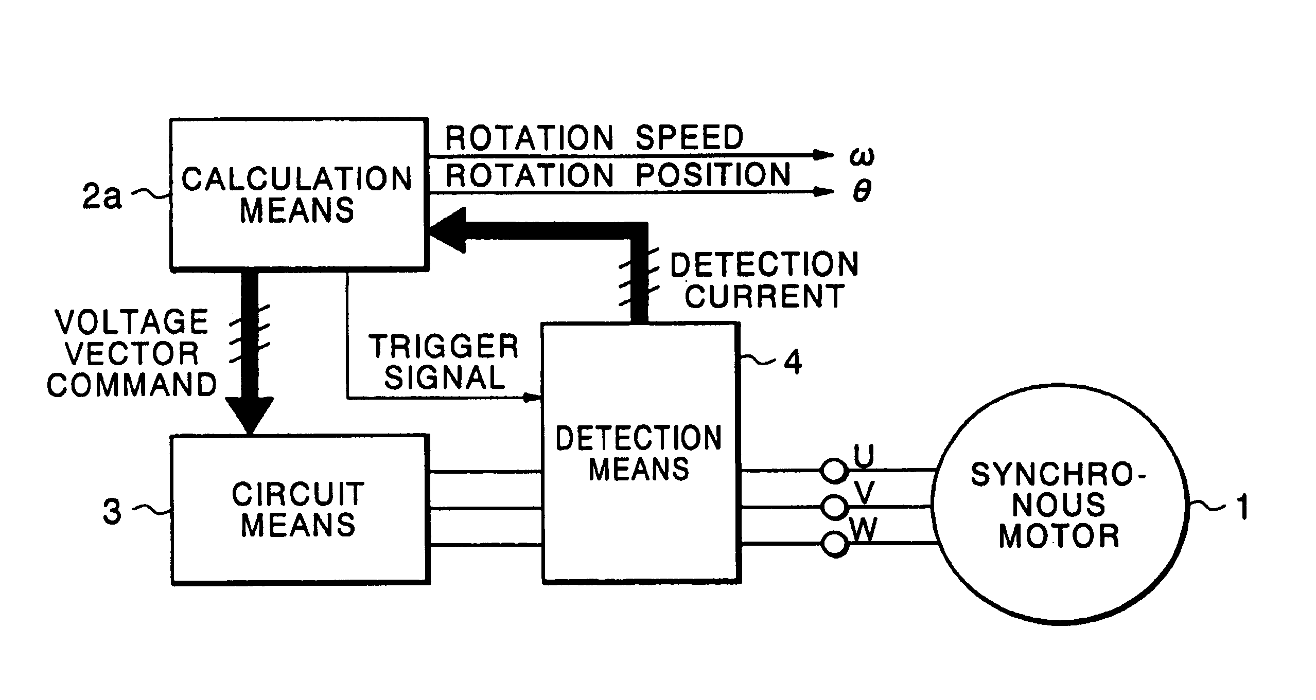
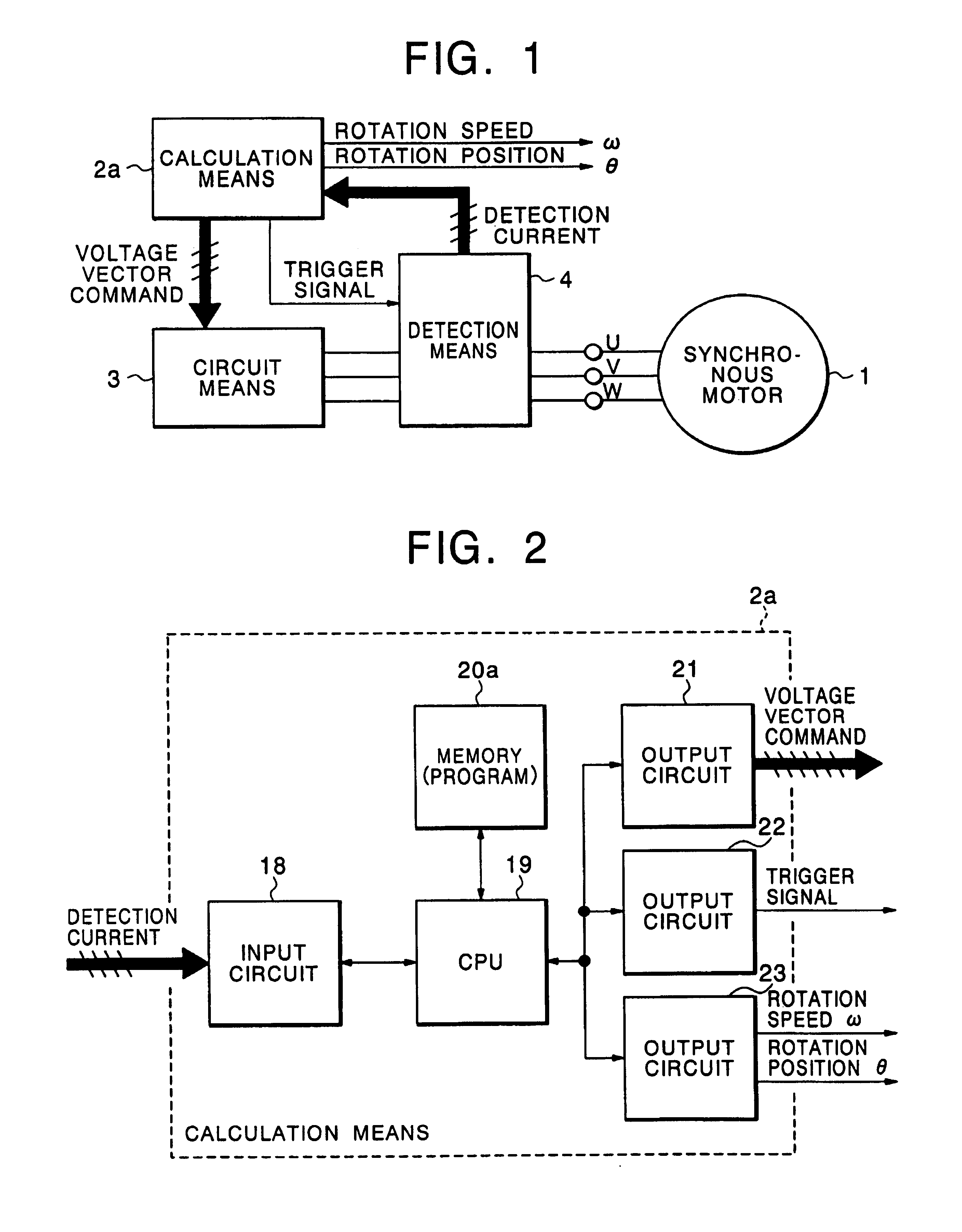
[0072]Hereinafter, an embodiment of the present invention will be described with reference to the drawings. FIG. 1 is a block structural view showing a rotation speed and rotation position detecting apparatus of a synchronous motor according to a first embodiment of the present invention. In FIG. 1, reference numeral 1 designates an embedded magnet type synchronous motor including three-phase windings; reference symbol 2a, calculation means for outputting a voltage vector command and a trigger signal and for outputting a rotation speed and a rotation position in an idle state; reference numeral 3, circuit means for applying voltages to respective phases of the synchronous motor 1 on the basis of the voltage vector command; and 4, detection means for detecting a current of the synchronous motor 1 on the basis of the trigger signal and outputting the current to the calculation means 2a.

[0073]Similarly to the conventional calculation means 2 shown in FIG. 22, the calculation means 2a ...

embodiment 2

[0112]In the embodiment 1, although the current phase θc1 has the accuracy within the range of ±22.5 degrees, the accuracy of the current phase θc1 can be improved by further introducing variables using currents ia1 and ib1 on the a-b coordinate axis.

[0113]Calculation currents iay1, iax1, ixb1, and iby·1 are defined by expression (26). iay1=G1⁢ ⁢(ia1-iy1)⁢⁢iax1=G1⁢ ⁢(ia1-ix1)⁢⁢ixb1=G1⁢ ⁢(ix1-ib1)⁢⁢iby1=G1⁢ ⁢(ib1+iy1)⁢⁢G1=12⁢ ⁢sin⁢ ⁢π8(26)

[0114]FIG. 14 shows relations between the current phase θc1 and the calculation currents ia1, ib1, ix1, iyl, iay1, iax1, ixb1 and iby·1. From the view, it is understood that the sign of any one of ia1, ib1, ix1, iy1, iay1, iax1, ixb1 and iby·1 is changed at intervals of 22.5 degrees. For example, θc1 is within the range of 0 to 22.5 degrees, ia1>0, ib1>0, ix1>0, iy1>0, iay1>0, iax1>0, ixb1>0, and iby·1>0, and in the case where θc1 is within the range of 22.5 to 45 degrees, ia1>0, ib1>0, ix1y1>0, iay1>0, iax1>0, ixb1>0, and iby·1>0. Accordingly, in t...

embodiment 3

[0118]According to the embodiment 1, although the value of Δθ in the expression (24) is obtained in advance by calculation, in the case where θs1 is sufficiently small, id1 is also sufficiently small, and consequently, |iq1 / id1| becomes a sufficiently large value, so that the value of Δθ may be made to be 90 degrees. In this case, the previously performed derivation of Δθ can be omitted.


PUM


Abstract

In a conventional rotation state detecting apparatus of a synchronous machine, since short-circuiting must be carried out twice or more when a rotation speed is detected, there have been problems in that it takes a time to detect a rotation state, and it takes a time to start up. A rotation state detecting apparatus for a synchronous machine according to the present invention has been made to solve the above problem, and includes a calculation unit for outputting a voltage vector command and a trigger signal and for outputting a rotation state of a synchronous machine having at least three windings in an idle state, a circuit unit for applying voltages to the respective phases of the synchronous machine on the basis of the voltage vector command, and a detection unit for detecting a current of the synchronous machine on the basis of the trigger signal and outputting a value of the detected current to the calculation unit. The calculation unit outputs a voltage vector for short-circuiting the respective phases of the synchronous machine, outputs trigger signals on at least one occurrence of the short-circuiting to produce current values from the detection unit multiple times, and calculates a rotation speed and a rotation position of the synchronous machine.

Description

TECHNICAL FIELD[0001]The present invention relates to a rotation state detecting apparatus for a synchronous machine and a rotation state detecting method for a synchronous machine, and particularly to an apparatus and a method for detecting a rotation state of a synchronous machine in an idle state, without using a position detector, such as an encoder.BACKGROUND ART[0002]In order to drive a synchronous machine such as a synchronous motor, information concerning the rotation speed and the rotation position of a rotor are indispensable. If a position detector such as an encoder is used, it is possible to know the rotation position of the rotor, and it is also possible to obtain the rotation speed from a change rate of the rotor position. However, there are defects in that the position detector is expensive, and complicated wiring is required in a case where an encoder is used. There have been invented many methods for driving a synchronous motor without using a position detector. In...

Claims


Application Information

Patent Timeline
IPC IPC(8): H02P6/18G01B7/30G01D5/242G01P3/44G01P3/46G01P13/04H02P6/06H02P6/08H02P6/182H02P6/28H02P21/00H02P21/18H02P21/24H02P23/16H02P27/04
CPCG01P3/44G01P13/045H02P6/165H02P6/185H02P25/022H02P6/17H02P25/024
Inventor KINPARA, YOSHIHIKOKAITANI, TOSHIYUKI
Owner MITSUBISHI ELECTRIC CORP
Features
  • R&D
  • Intellectual Property
  • Life Sciences
  • Materials
  • Tech Scout
  • Unparalleled Data Quality
  • Higher Quality Content
  • 60% Fewer Hallucinations
Learn More