Switched-current power converter

a power converter and switching-current technology, applied in the field of power converters, can solve problems such as poor dynamic respons

Inactive Publication Date: 2005-12-27
HERBERT EDWARD
View PDF1 Cites 23 Cited by
  • Summary
  • Abstract
  • Description
  • Claims
  • Application Information

AI Technical Summary

Benefits of technology

[0015]Another embodiment of the invention incorporates switched-charge ...

Problems solved by technology

Poor dynamic response is a problem in many other general purpose power supplies as well, whenever fast changes in load occur.
An exampl...

Method used


Image

  • Switched-current power converter
  • Switched-current power converter
  • Switched-current power converter

Examples


Embodiment Construction

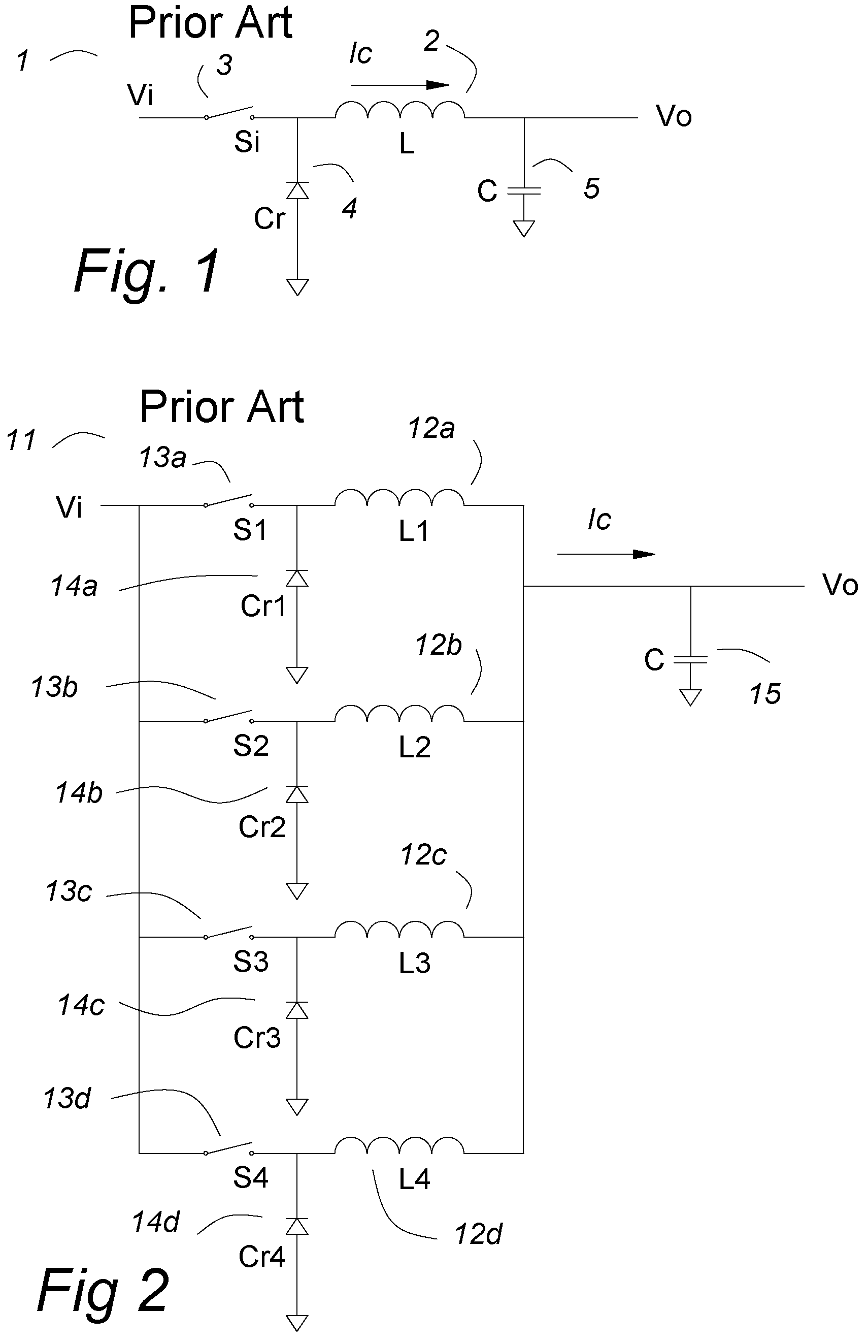
[0036]FIG. 1 shows a prior art buck converter 1. A switch 3 is pulse width modulated to provide an average voltage equal to the duty cycle times the input voltage Vi to an inductor 2. The inductor 2 and a capacitor 5 cooperate as an output filter to provide a smooth output voltage Vo. A catch diode 4 conducts current into the inductor 2 when the switch 3 is open. In modern power converters, the switch 3 and the catch diode 4 may be MOSFETs.

[0037]FIG. 2 shows a prior art multi-phase buck converter 11. A plurality of input switches 13a–13d are pulse width modulated to provide an average voltage equal to the duty cycle times the input voltage V1 to a plurality of inductors 12a–12d. The plurality of inductors 12a–12d and an output capacitor 15 cooperate as an output filter to provide a smooth output voltage Vo. A plurality of catch diodes 14a–14d conduct currents into the plurality of inductors 12a–12d when any of the plurality of switches 13a–13d are open. In modern power converters, t...


PUM


Abstract

In a switched-current power converter, a plurality of constant current sources provide equal currents to a plurality of switch pairs that may direct the several currents either to the return or to the output capacitors and the load. In another embodiment of the invention, internal switches may short circuit the several current sources and a plurality of switches may switch the several currents to the output capacitor and the load when the internal switches are not short circuits. A voltage control circuit is shown in which a resistor ladder network is the references for a number of comparators which directly control the plurality of switches. An alternative voltage control circuit uses two comparators and an up-down counter to control the switches.

Description

CROSS REFERENCE TO RELATED APPLICATIONS[0001]This application claims priority to the following provisional patent applications: Ser. No. 60 / 473,075 “Switched-current Power Converter”, filed 23 May, 2003; Ser. No. 60 / 477,417 “Fast Transition Power Converter for Processors Using Switched-Current and Switched Charge”, filed 9 Jun., 2003; Ser. No. 60 / 479,706 “Parallel Current Sources for Switched-Current Power Converters”, filed 19 Jun., 2003; Ser. No. 60 / 481,022 “Voltage Control for Switched-Current Power Converters”, filed 25 Jun., 2003; and Ser. No. 60 / 481,414 “Voltage Control for Switched-Current Power Converters, filed 24 Sept., 2003. U.S. Pat. No. 4,665,357, “Flat Matrix Power Supply”, issued on May 12, 1987 and U.S. Pat. No. 6,121,761 “Fast Transition Power Supply”, Edward Herbert, issued on Sept. 19, 2000 are cited as references.BACKGROUND OF INVENTION[0002]This invention relates to power converters, particularly power converters having a very fast dynamic response to changes in...

Claims


Application Information

Patent Timeline
IPC IPC(8): H02M3/158
CPCH02M3/1584
Inventor HERBERT, EDWARD
Owner HERBERT EDWARD
Why Eureka
Try Eureka