System for and method of interconnecting high-frequency transmission lines

a high-frequency transmission line and high-frequency technology, applied in the direction of waveguides, high-frequency circuit adaptations, coupling device connections, etc., can solve the problems of high-frequency transmission line connecting systems, increase system costs, impedance mismatch, etc., to achieve excellent high-frequency characteristics, good impedance matching, and uniform interconnection quality

Inactive Publication Date: 2005-12-27
RYOWA DENSHI
View PDF7 Cites 25 Cited by
  • Summary
  • Abstract
  • Description
  • Claims
  • Application Information

AI Technical Summary

Benefits of technology

[0028]It is therefore an object of the present invention to provide a system for and a method of interconnecting first and second high-frequency transmission lines inexpensively, simply, and accurately with a strong mechanical connection, while achieving a good impedance matching in a wide frequency range in excess of 10 GHz at the junction therebetween, according to a highly reproducible connecting technique (fixing technique) which is suitable for realizing excellent high-frequency characteristics. The highly reproducible technique refers to a process of achieving stably a uniform interconnection quality in repeated cycles of connecting first and second transmission lines.

Problems solved by technology

However, using high-frequency coaxial connectors tends to increase the system cost.
However, the high-frequency transmission line connecting systems according to the prior art 1 and the prior art 2 have various problems as described below.
Since the central conductor 8 of the coaxial cable 6 needs a certain length of its bare wire strip to be soldered, the bare wire strip holds a large stray inductance which leads to an impedance mismatch, and also causes a large reflection loss.
The large stray capacitance also leads to an impedance mismatch and gives rise to a large reflection loss.
It is also difficult to keep the bare wire strip of the central conductor 8 constant in length in mounting the coaxial cable 6 on the multilayer circuit board 2.
As a result, it is difficult to keep the connection between the coaxial cable 6 and the multilayer circuit board 2 in constant physical configuration and to keep constant electrical characteristics.
Similarly, the central conductor 8 and the via hole 4 need to be soldered with skill and expertise because the space available for soldering is not enough.
Therefore, there is difficulty in positioning and soldering the coaxial cable 6.
However, since solder is used to connect the central conductor 8 and the signal conductor 34 to each other without any fixing mechanism, intricate workmanship is required to apply an appropriate amount of solder to an appropriate area for making reliable and economical solder joints.
Stated otherwise, the efficiency with which the connection structure is assembled is low, and the time required to assemble the connection structure is long, resulting in a reduced yield.
According to the prior art 2, as with the prior art 1, inasmuch as the coaxial cable 6 is required to be positioned on and fixed to the flat surface of the multilayer circuit board 2, difficulty has been encountered in positioning and soldering the coaxial cable 6, making it difficult to maintain a uniform interconnection quality.

Method used


Image

  • System for and method of interconnecting high-frequency transmission lines
  • System for and method of interconnecting high-frequency transmission lines
  • System for and method of interconnecting high-frequency transmission lines

Examples


Embodiment Construction

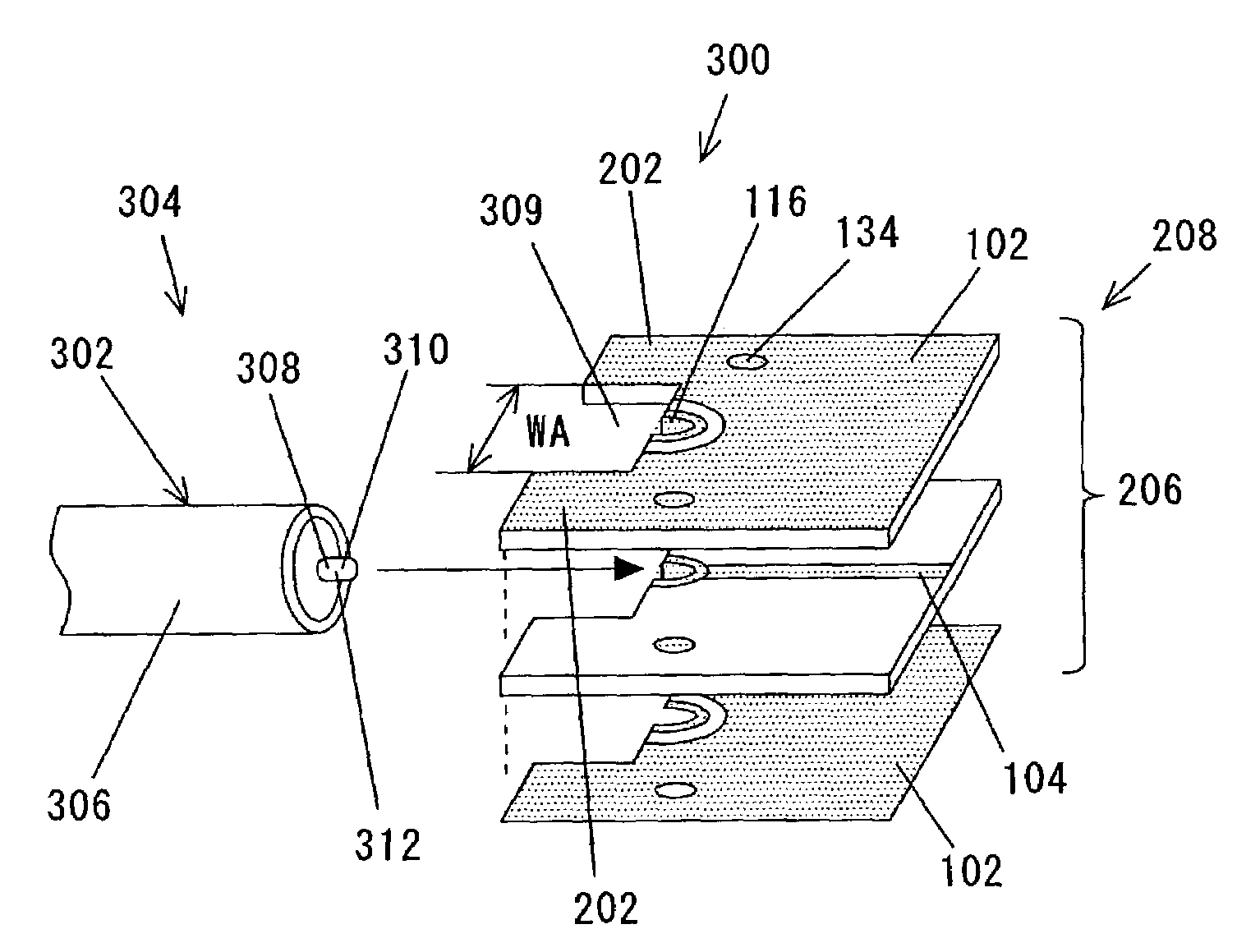
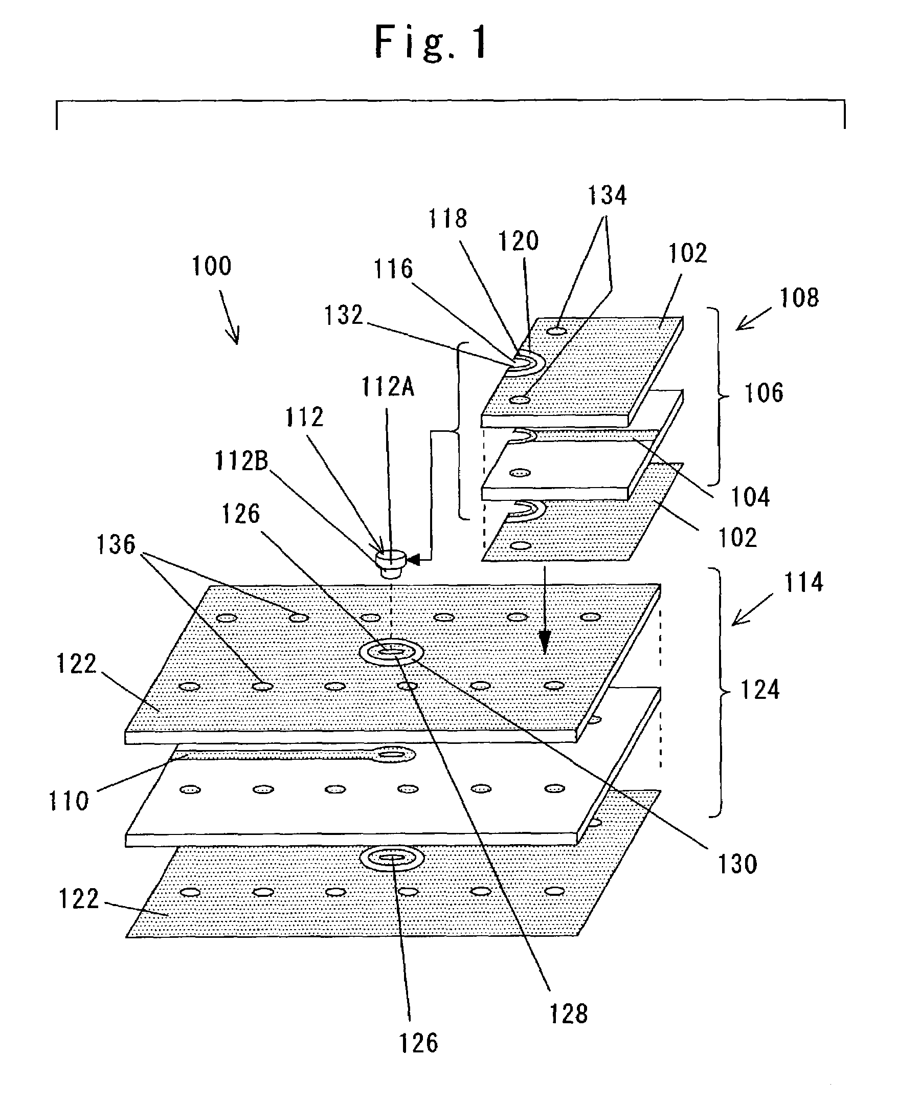
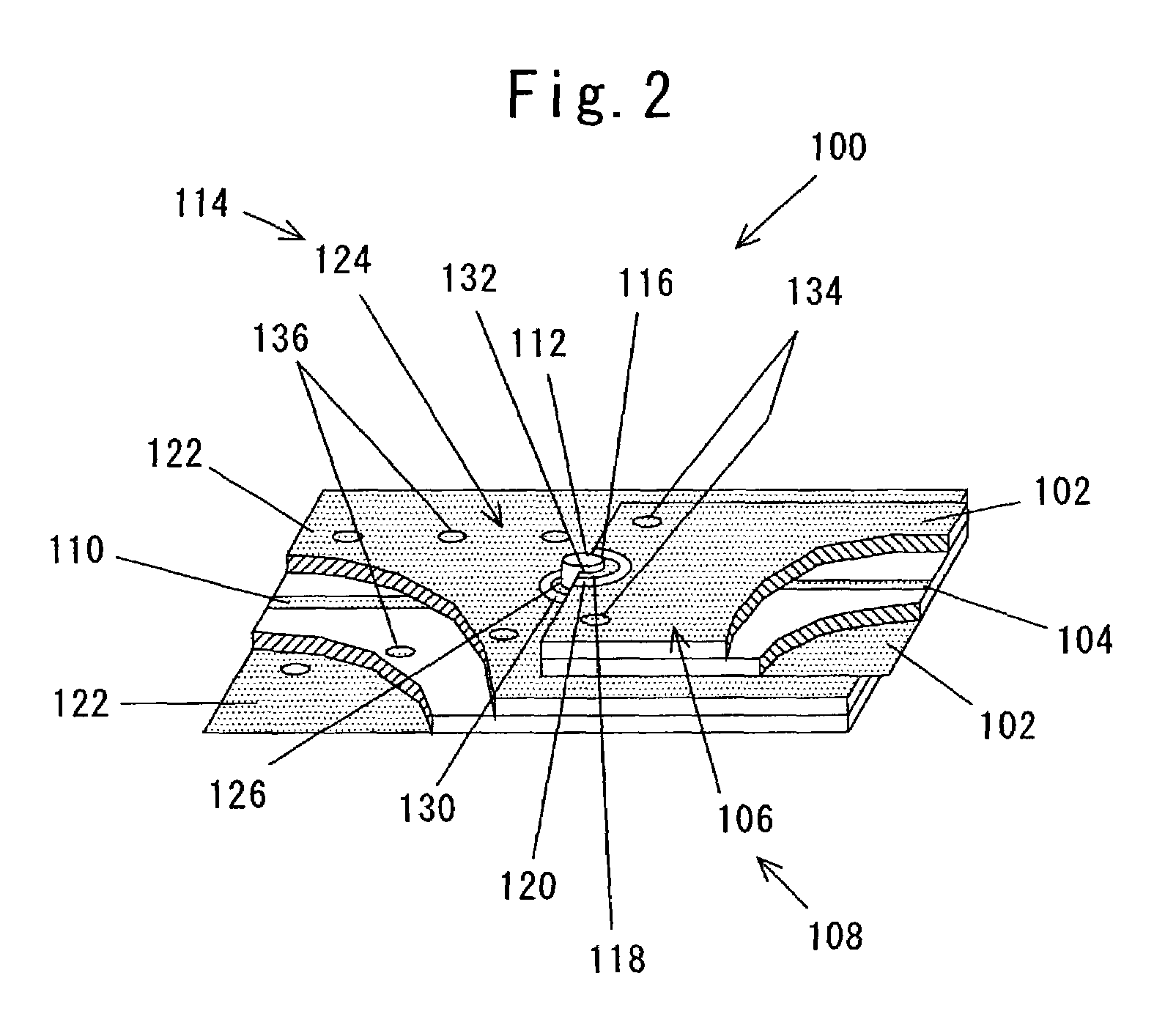
[0073]Preferred embodiments of the present invention will be described below with reference to the drawings. Those parts of the embodiments shown in FIGS. 1 through 22 which are identical to those shown in FIGS. 23 through 26 are denoted by identical reference characters, and will not be described in detail below.

[0074]FIG. 1 shows in exploded perspective, a system 100 for interconnecting high-frequency transmission lines according to an embodiment of the present invention, and FIG. 2 shows in perspective, partly broken away, a portion of the system for interconnecting high-frequency transmission lines shown in FIG. 1.

[0075]As shown in FIGS. 1 and 2, the system 100 for interconnecting high-frequency transmission lines includes a first transmission line 108 and a second transmission line 114 which is electrically connected to the first transmission line 108.

[0076]The first transmission line 108 comprises a multilayer circuit board 106 of sandwiched structure having three conductive l...


PUM


Abstract

A cut via is formed in an end of a multilayer circuit board of the first transmission line, and a clearance is provided between the cut via and a ground pattern for achieving an impedance matching between the first and second transmission lines. The cut via of a first transmission line which may be a stripline or a microstrip line, and an electrode of the second transmission line are connected to each other, and ground patterns of the first and second transmission lines are connected to each other. The first and second transmission lines have respective signal lines positioned substantially coaxially with each other.

Description

BACKGROUND OF THE INVENTION[0001]1. Field of the Invention[0002]The present invention relates to a system for and a method of interconnecting a first high-frequency transmission line such as a multilayer circuit board having a stripline or a microstrip line, for example, and a second high-frequency transmission line such as a coaxial cable or a multilayer circuit board, for example, while providing a good impedance matching therebetween.[0003]2. Description of the Related Art[0004]The recent technological advances in IT (Information Technology) have resulted in a massive growth of information communication networks processing electric signals in a frequency range from several hundreds MHz to GHz. For example, radio waves in the GHz frequency band are used by information and communication devices and instruments such as cellular phones and wireless LAN (Local Area Network) terminals and the ITS (Intelligent Transportation System). To meet increasing demands for more and more radio wa...

Claims


Application Information

Patent Timeline
Patent Type & Authority Patents(United States)
IPC IPC(8): H05K1/14H01P1/04H01P5/02H01P5/08H01R9/05H05K1/00H05K1/02H05K3/00H05K3/32H05K3/34H05K3/36H05K3/40H05K3/42
CPCH01P1/047H01P5/085H01R9/0515H05K1/0222H05K1/0251H01P5/02H01L2224/48091H01R24/50H05K1/0298H05K3/0052H05K3/325H05K3/3405H05K3/3447H05K3/368H05K3/403H05K3/42H05K2201/0311H05K2201/0715H05K2201/09618H05K2201/09809H05K2201/10303H05K2201/10356H01L2224/45144H01L2924/00014H01L2924/00H01L2924/19107H01L2224/4903
Inventor MIYAZAWA, YASUNORIKAMINISHI, KATSUJI
Owner RYOWA DENSHI
Why Eureka
Try Eureka