Low noise full integrated multilayers magnetic for power converters

Inactive Publication Date: 2005-12-27
DET INT HLDG LTD
View PDF18 Cites 41 Cited by
  • Summary
  • Abstract
  • Description
  • Claims
  • Application Information

AI Technical Summary

Benefits of technology

[0007]Power processing devices according to this invention offer a construction technique of the main transformer which also extends to all the magnetic elements, wherein the parasitic elements of the circuit are minimized. At the same time the common mode current injected to the secondary via the inter-winding capacitance is reduced and even eliminated. The cons

Problems solved by technology

This will sacrifice the pow

Method used


Image

  • Low noise full integrated multilayers magnetic for power converters
  • Low noise full integrated multilayers magnetic for power converters
  • Low noise full integrated multilayers magnetic for power converters

Examples


Example

[0027]The multilayer planar magnetic, in which the windings are continuous flat copper spirals located on separate dielectric substrates, have been used before for signal and data processing. In the power conversion field the multilayer magnetic have been used since 1986. However, there are several limitations with multilayer magnetic which prevented this technology from a large utilization. Decreasing the height of the magnetic, by utilizing flat windings, leads to an increased footprint. As a result a large portion of the board on which the multilayer planar magnetic is mounted, cannot be used for another purpose, having a negative impact on the volumetric efficiency. Another limitation associated with planar multilayer magnetic is the increased inter-winding capacitance, which leads to higher switching losses on the switching elements and a larger common mode current injected to the secondary via the capacitance between primary and secondary windings. The parasitic elements such ...


PUM


Abstract

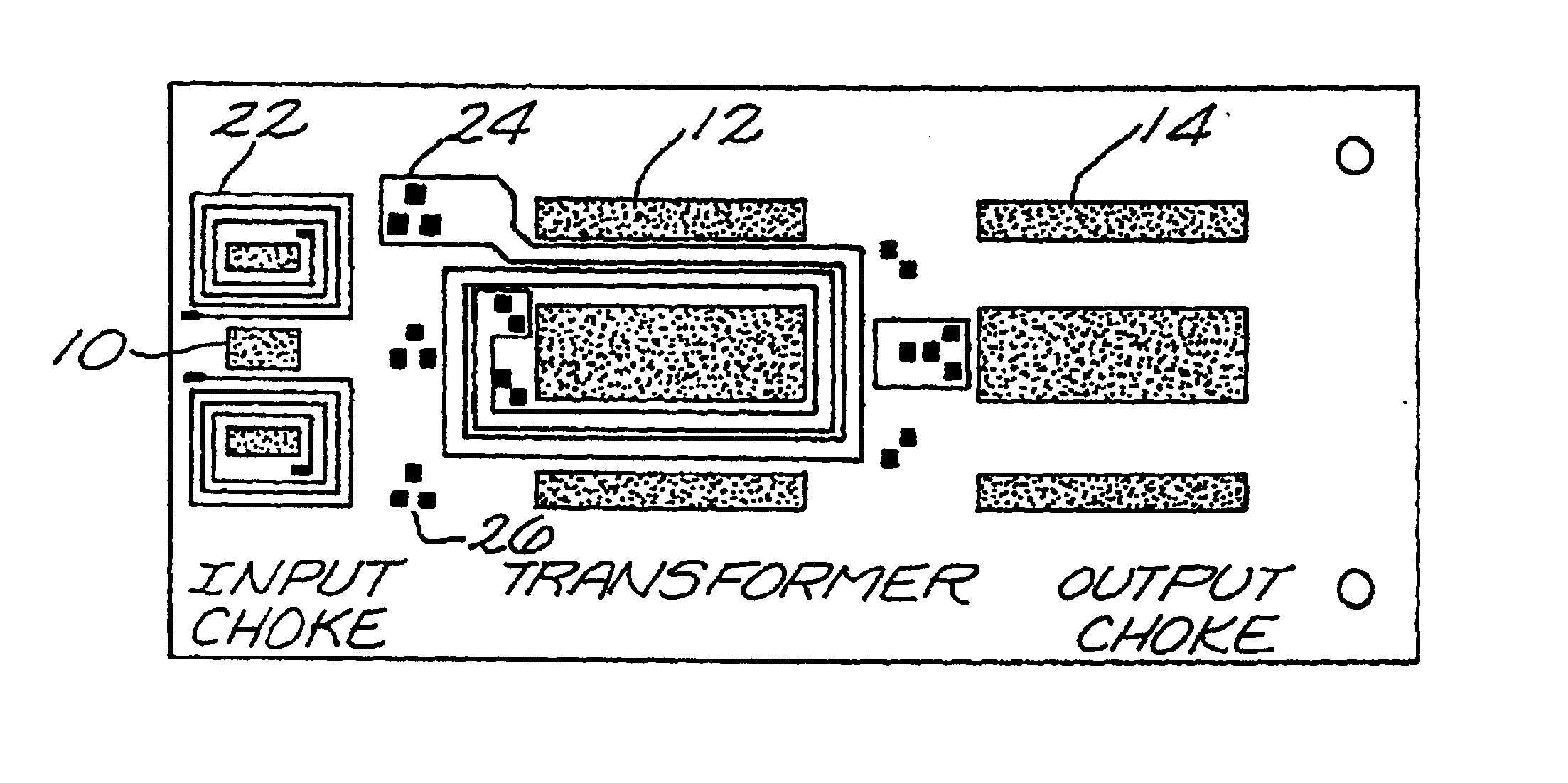
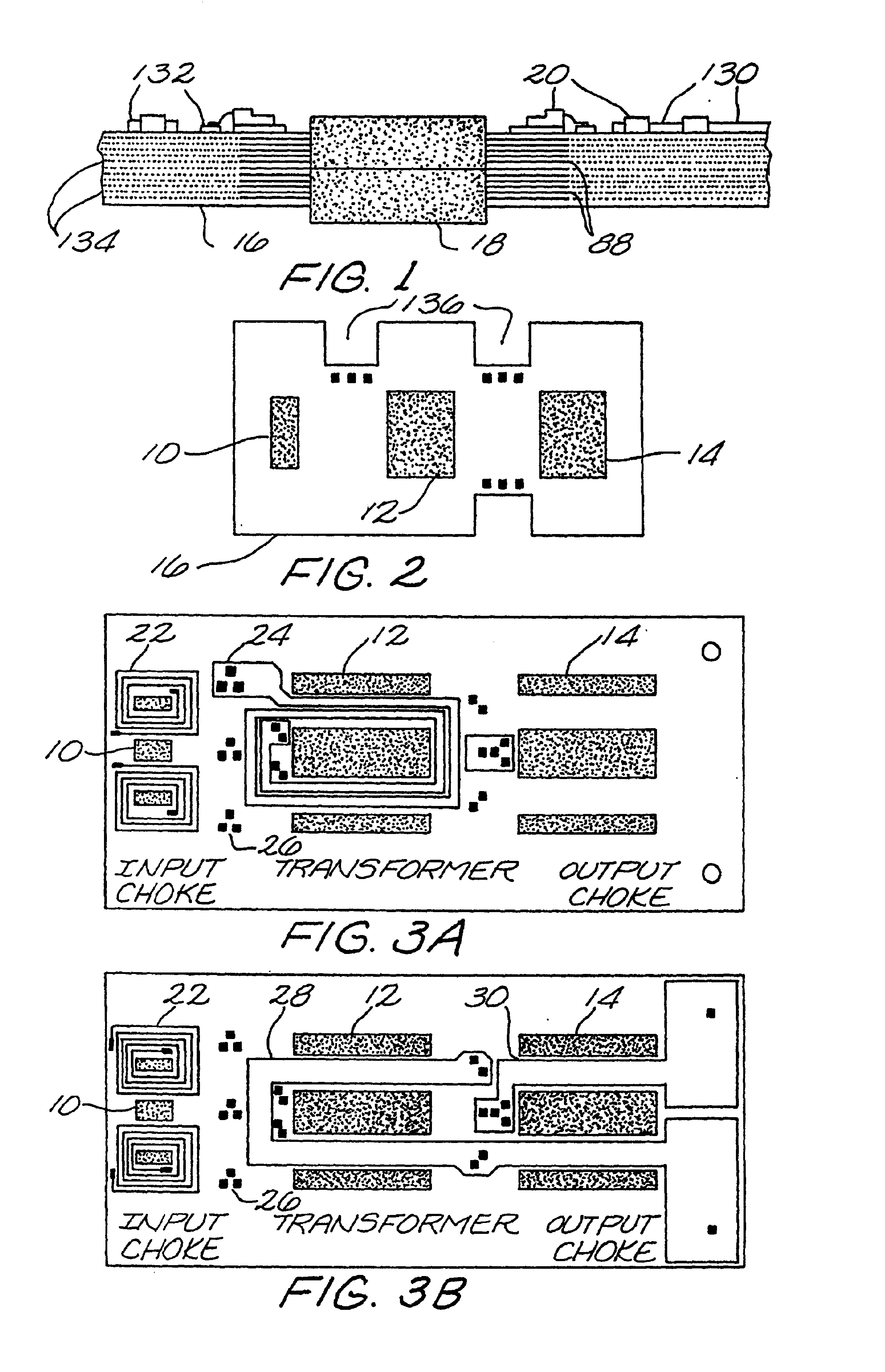
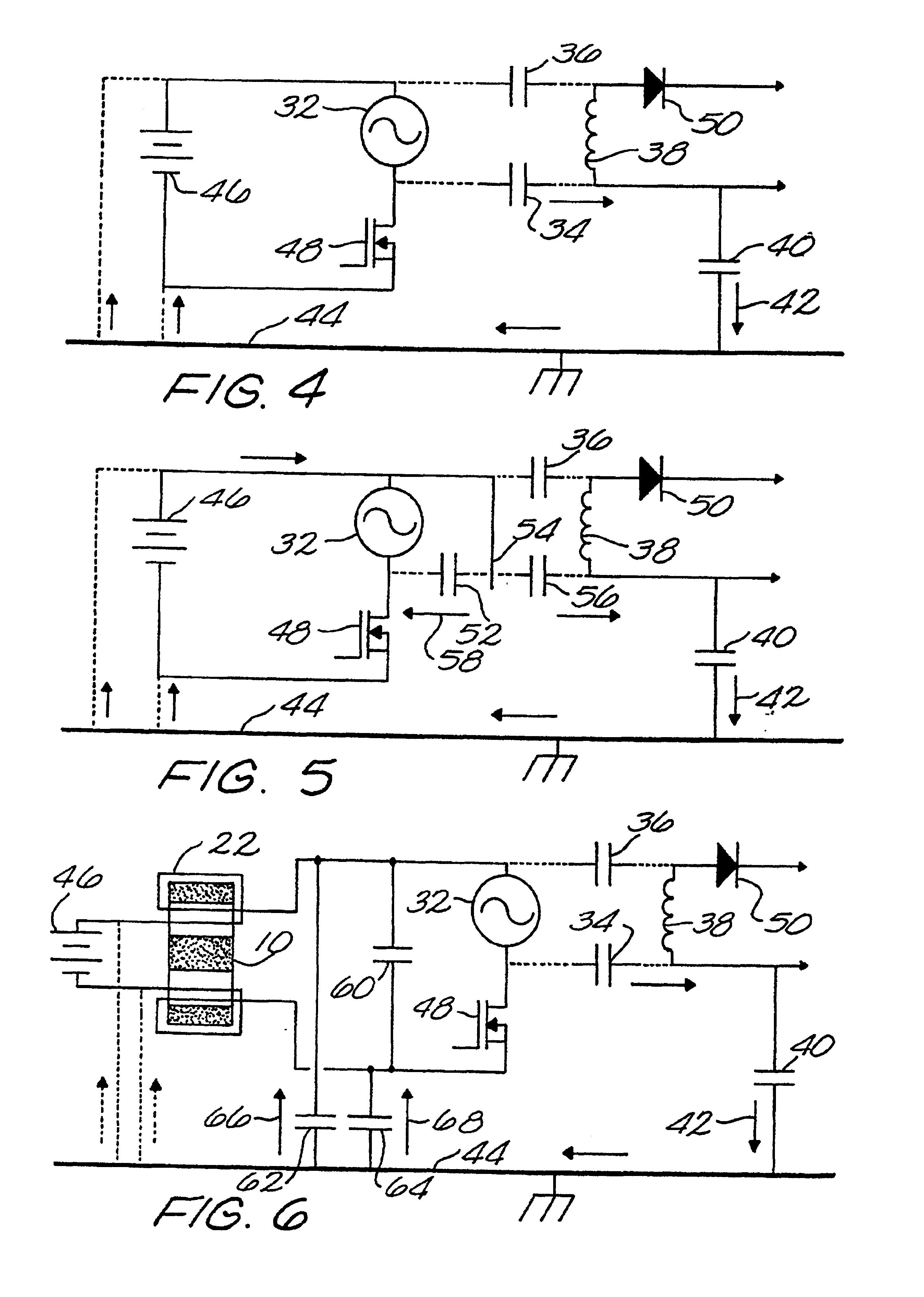
A multilayer structure in which all the magnetic elements have the windings edged in the inner layers and the magnetic core which surrounds the winding has the legs penetrating through the multilayer structure. The interconnection between the magnetic elements and the rest of electronic components is done through the layers of the multilayer board, horizontally and vertically through via. For higher power components special cuts are performed in the multilayer board to accommodate the body of the components which may be connected to an external heatsink. The winding arrangement in the transformer is done in a such way to minimize and even eliminate the common mode noise injected through the capacitance between primary and secondary winding. The input filter is constructed to exhibit a differential and a common mode impedance. Supplementary capacitors are incorporated in the multilayers structure to offer a low impedance to the noise to short it to the source, or for injecting currents of opposite polarity to cancel the common mode current transferred through the transformer's inter winding capacitance and through the parasitic capacitance of the switching elements to the secondary. The insulation between winding can be in accordance with the safety agency requirements, allowing much shorter creapage distances inside of the multilayer PCB structure than in the air due to the compliance with coating environment.

Description

RELATED APPLICATIONS[0001]This is a continuation of U.S. patent application Ser. No. 08 / 351,943, filed on Dec. 8, 1994, now U.S. Pat. No. 5,990,776, and entitled “Low Noise Full Integrated Multilayer Magnetic for Power Converters,” incorporated herein by reference.FIELD OF THE INVENTION[0002]This invention relates to DC-to-DC converters, DC-to-AC, AC-to-AC and AC-to-DC converters. The major characteristic of this power conversion technique is that all the magnetic elements are implemented on the same multilayers structure, and the power transfer is made highly efficient and common mode noise is minimized.BACKGROUND OF INVENTION[0003]There is a continuing industry demand for increasing power density, which means more power transferred in a given volume. A method for increasing the power transfer through the converter is to increase the switching frequency in order to minimize the size of magnetics and capacitors. Using prior art topologies such as forward or flyback, which employ “ha...

Claims


Application Information

Patent Timeline
IPC IPC(8): H01F27/28H05K1/00H05K1/16
CPCH01F27/2804H05K1/165H05K1/0298H05K2201/086H05K2201/09063H05K2201/10166
Inventor JITARU, IONEL
Owner DET INT HLDG LTD
Why Eureka
Try Eureka