Method and apparatus for tracing packets

a packet and packet technology, applied in the field of network security, can solve the problems of increasing the number of vulnerability points from which malicious individuals can launch attacks, increasing the size of the internet, and increasing the threat posed by individuals, so as to facilitate the identification of intrusion locations, improve packet networks, and eliminate problems caused

Inactive Publication Date: 2005-12-27
STRAGENT
View PDF4 Cites 80 Cited by
  • Summary
  • Abstract
  • Description
  • Claims
  • Application Information

AI Technical Summary

Benefits of technology

[0022]It is thus a general object of the present invention to provide improved packet networks.
[0023]It is another object of the present invention to eliminate problems caused by malicious packets in a network.
[0024]It is a further object of the present invention to identify malicious packets to facilitate identifying their intrusion locations into the network.
[0025]It is a further object of the present invention to quickly identify ingress poi

Problems solved by technology

Along with rapid growth of the Internet have come problems caused by malicious individuals or pranksters launching attacks from within the network.
As the size of the Internet continues to grow, so does the threat posed by these individuals.
The ever-increasing number of computers, routers and connections making up the Internet increases the number of vulnerability points from which these malicious individuals can launch attacks.
Attacks carried out on the Internet often consist of malicious packets being injected into the network.
Such a computer or device can be compromised and configured to place malicious packets onto the network.
The flood of packets can be targeted to a specific device on the network, for example a corporate web site, thus causing the device to become overwhelmed and shutdown.
Spoofing involves associating bogus Internet Protocol (IP) addresses with transmitted packets, thus making the packets' origins impossible to determine based upon looking only at a received packet.
Locating the origin of a network attack is further complicated because coordinated attacks can be employed.
While single packet attacks are not as well publicized as multi-packet attacks, they are becoming more common and they are capable of inflicting significant damage to vulnerable networks.
At present, it is extremely difficult to detect single packet attacks in a timely manner using known methods of intrusion detection, which exacerbates the challenge in dealing with them.
Much of the

Method used


Image

  • Method and apparatus for tracing packets
  • Method and apparatus for tracing packets
  • Method and apparatus for tracing packets

Examples


Embodiment Construction
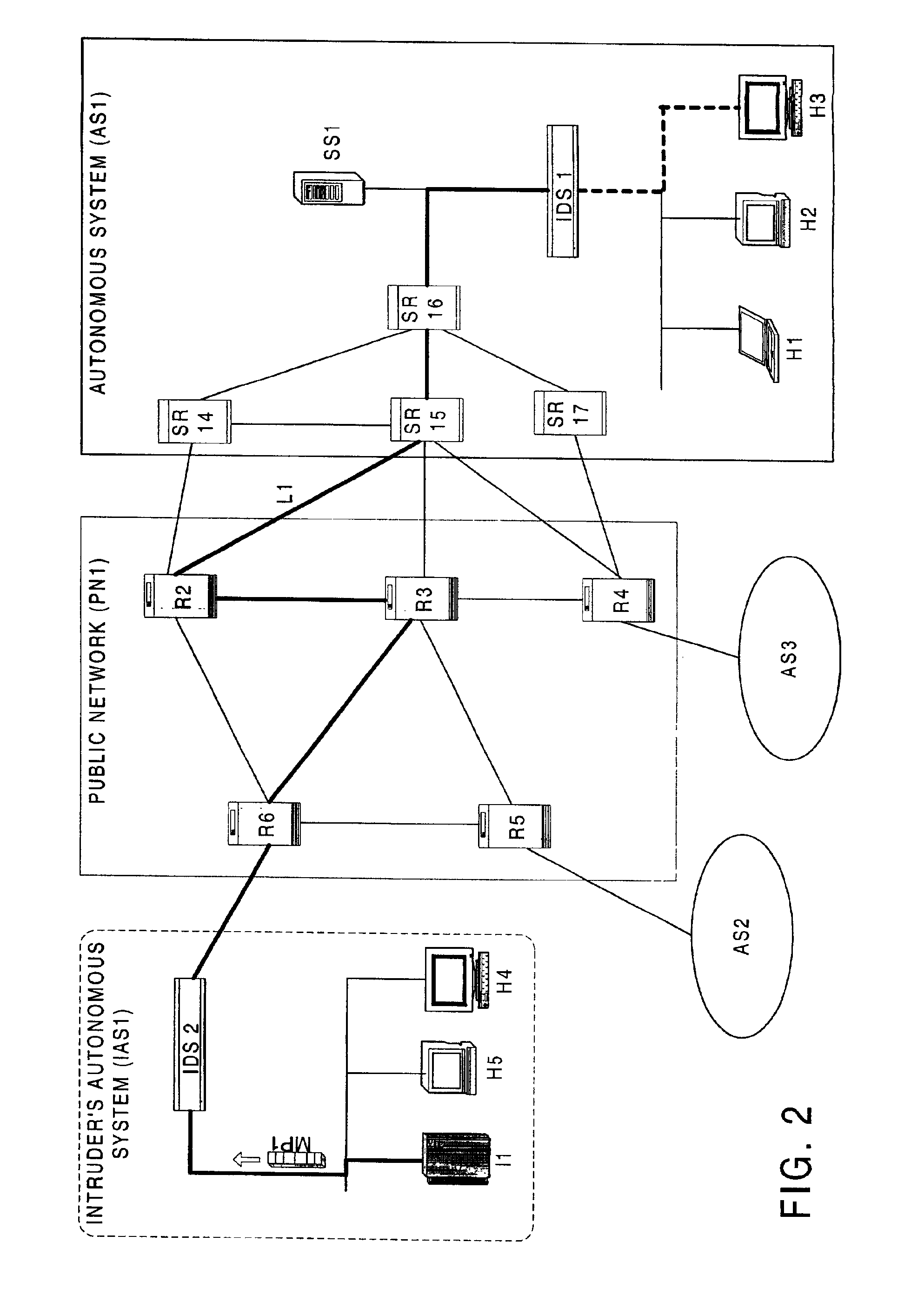
[0034]FIG. 2

[0035]A preferred embodiment uses a server and one or more specially configured network components, or devices, such as a router, within an autonomous system (AS) to determine the ingress point, or location, for a malicious packet (MP1). FIG. 2 illustrates an embodiment that may be used with an Internet Protocol network. More particularly, FIG. 2 is broken into three general areas enclosed within borders with communication media, such as links, carrying data traffic across the network, connecting the general areas. Links serve as a transmission media for data and signals on the network and may be comprised of wire, optical fiber, radio frequency (RF) transponders, or the like.

[0036]The rightmost portion of FIG. 2 denotes an AS, shown as AS1, enhanced by the addition of a source path isolation server (SS1) and network components, here routers, modified to work as source path isolation routers (SRs), denoted by SR14-17, respectively. Also included within AS1 is a detection...


PUM


Abstract

A system and method for performing source path isolation in a network. The system comprises an intrusion detection system (IDS), a source path isolation server (SS1) and at least one router configured to operate as a source path isolation router (SR1) operating within an autonomous system. When IDS detects a malicious packet, a message is sent to SS1. SS1 in turn generates a query message (QM) containing at least a portion of the malicious packet. Then, QM is sent to participating routers located one hop away. SR1 uses the query message to determine if it has observed the malicious packet by comparing it with locally stored information about packets having passed through SR1. SR1 sends a reply to SS1, and SS1 uses the reply to identify the ingress point into the network of the malicious packet.

Description

CROSS REFERENCE TO RELATED APPLICATIONS[0001]The instant application claims priority from provisional application Ser. No. 60 / 212,425, filed Jun. 19, 2000, which is hereby incorporated by reference herein in its entirety. The instant application is also related to U.S. patent application Ser. No. 09 / 881,145, having assignee in common with the instant application and filed Jun. 14, 2001, entitled METHOD AND APPARATUS FOR IDENTIFYING A PACKET, the contents of which are hereby incorporated by reference in its entirety.BACKGROUND OF THE INVENTION[0002]1. Field of the Invention[0003]The present invention relates generally to the field of network security and more specifically to using low overhead methods for identifying the intrusion location of a packet in a network.[0004]2. Description of Prior Art[0005]Availability of low cost computers, high speed networking products, and readily available network connections has helped fuel proliferation of the Internet. This proliferation has caus...

Claims


Application Information

Patent Timeline
IPC IPC(8): G06F11/30G06F15/00
CPCH04L63/1416H04L2463/146
Inventor SANCHEZ, LUISSTRAYER, WILLIAM TIMOTHYPARTRIDGE, CRAIG
Owner STRAGENT
Why Eureka
Try Eureka