Automatic teller machine

a technology teller machine, which is applied in the direction of automatic teller machine, atm details, instruments, etc., can solve the problems of shortening the verification time and increasing the transportation speed, and increasing the incidence of genuine notes being rejected, so as to maintain the regular high-speed performance and reduce the occurrence of genuine notes. , the effect of high accuracy

Inactive Publication Date: 2006-01-03
HITACHI OMRON TERMINAL SOLUTIONS CORP
View PDF13 Cites 30 Cited by
  • Summary
  • Abstract
  • Description
  • Claims
  • Application Information

AI Technical Summary

Benefits of technology

[0007]The object of the present invention is to provide an automatic teller machine capable of verification with high accuracy and less liable to reject genuine notes while maintaining the regular high-speed performance. The present invention is suitable for automatic teller machines (ATM) installed in banking facilities.

Problems solved by technology

However, if one tries to securely reject elaborate counterfeit notes, a percentage of genuine notes being rejected increases due to sensor fluctuation, fluctuation of transport condition or the like, which has been a problem.
However, to this end, it is necessary to shorten verification time and increase transportation speed.
Since high speed and high verification accuracy are not compatible, another problem is that when high speed in process is pursued, the incidence of genuine notes being rejected increases.
Even if rejected notes account for a small proportion of notes received by the ATM, they definitely increase the transaction time by the length of time for re-verification.
Because the second-stage bill validator was an auxiliary unit for man-operated classification of counterfeits and genuine notes, this device could not be applied to automatic teller machines installed in banking facilities.

Method used


Image

  • Automatic teller machine
  • Automatic teller machine
  • Automatic teller machine

Examples


embodiment 1

(Embodiment 1)

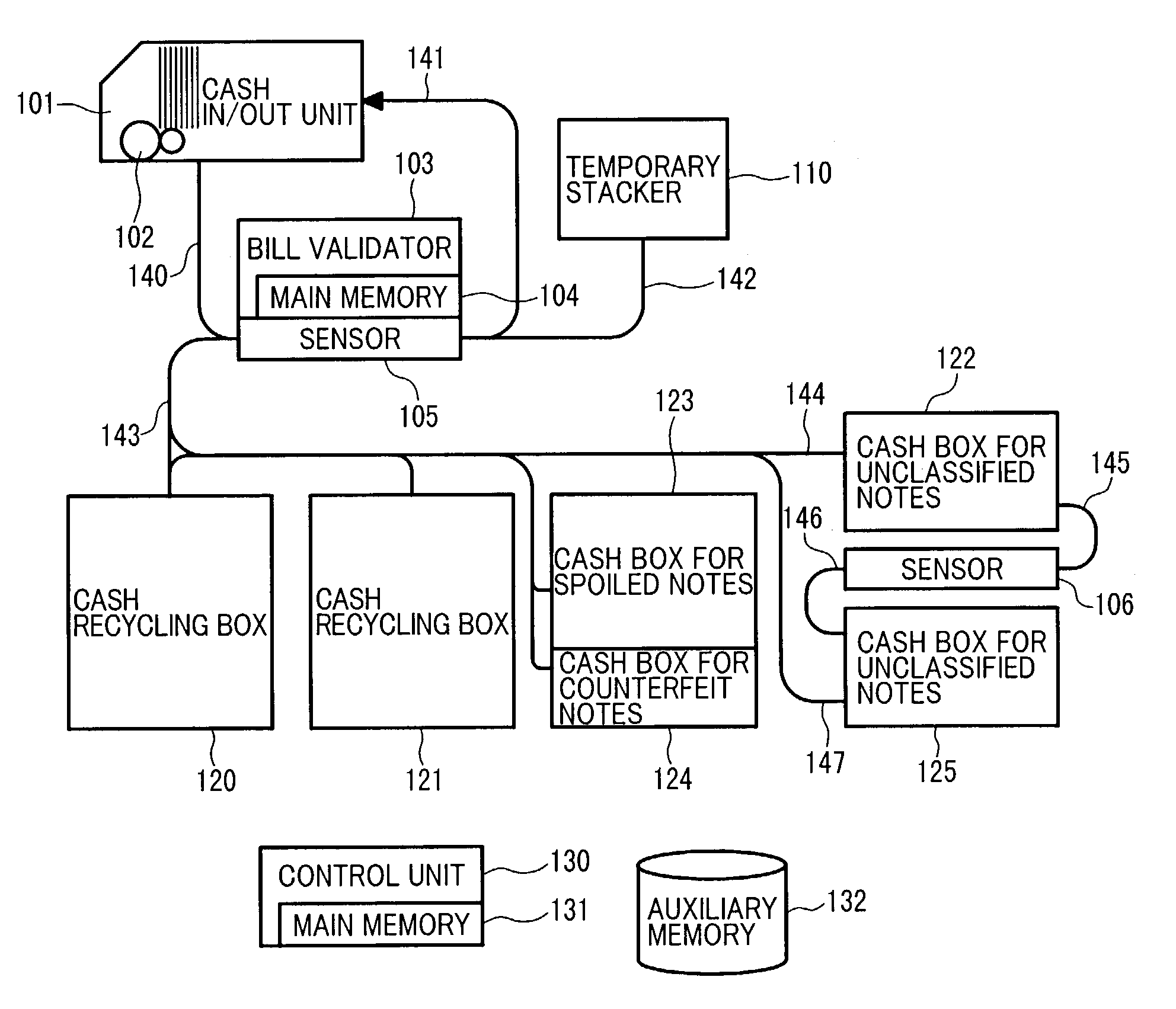
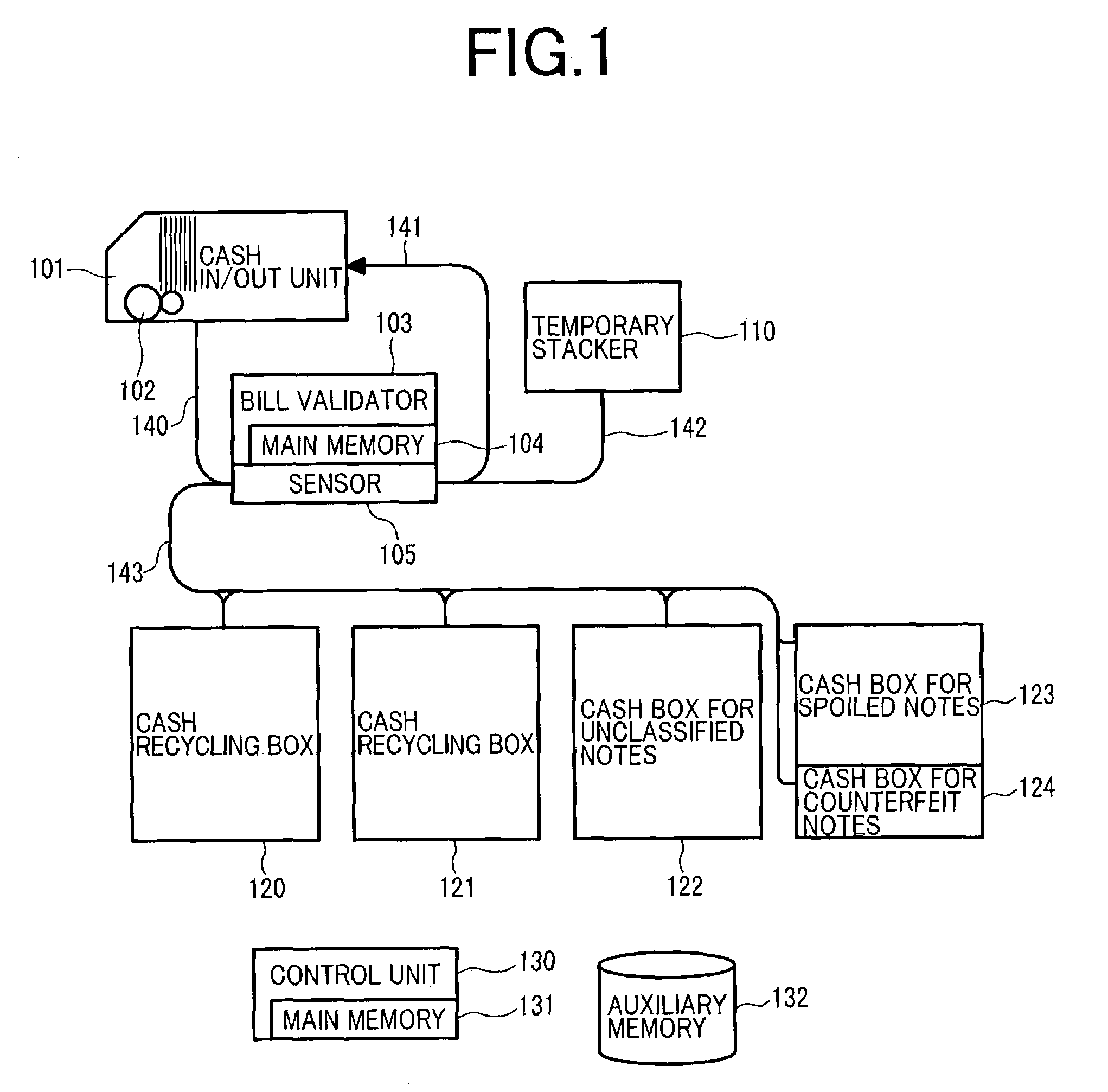
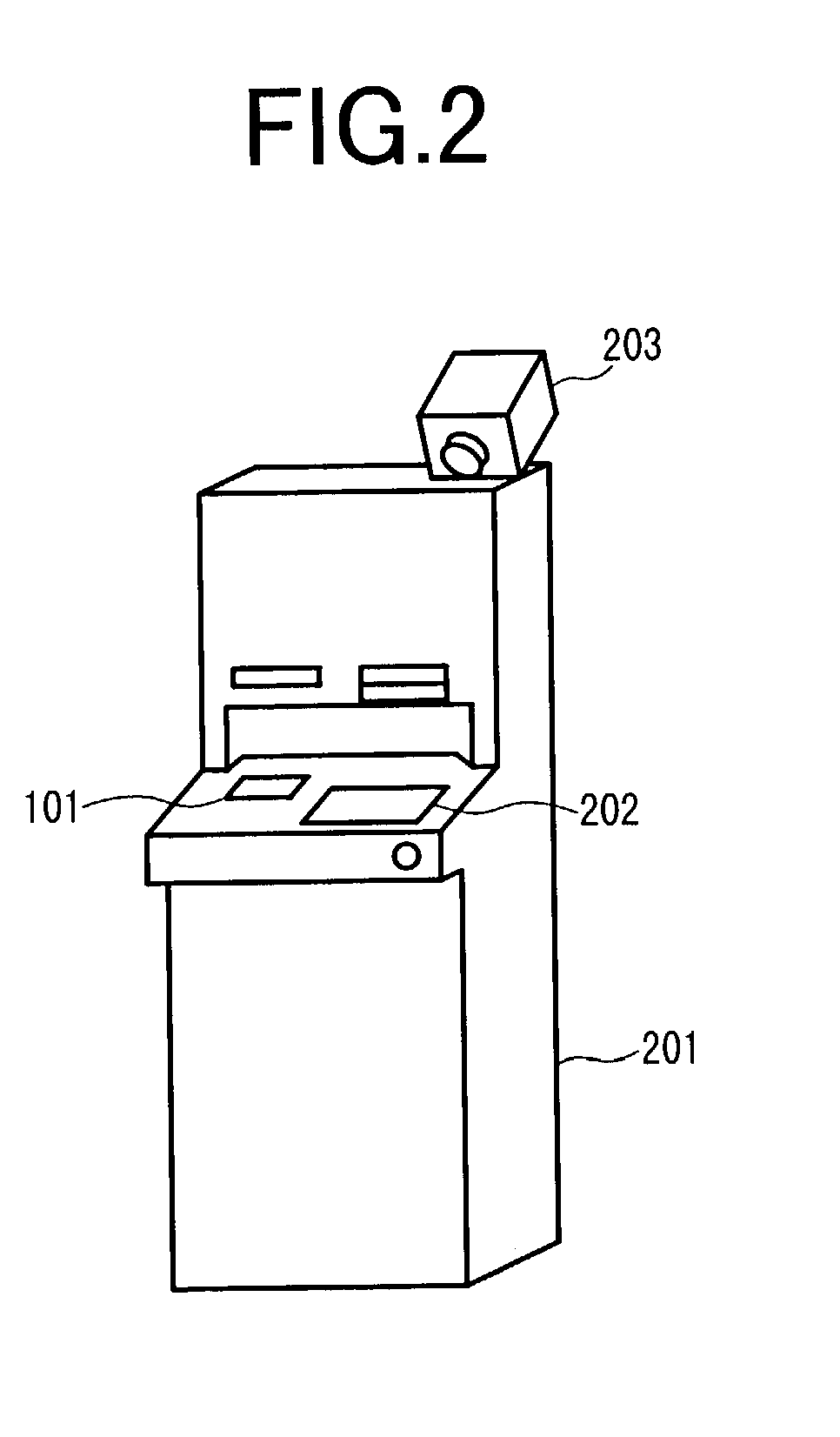
[0026]A first embodiment of the invention will be described with reference to the accompanying drawings. FIG. 1 is a block diagram of an automatic teller machine according to the present invention. Reference numeral 101 denotes a cash in / out unit, 102 denotes a bill separator, 103 denotes a bill validator, 104 denotes the main memory of the bill validator, 105 denotes a sensor, 110 denotes a temporary stacker, 120 and 121 denote cash recycling boxes, 122 denotes a cash box for unclassified notes, 123 denotes a cash box for spoiled notes, 124 denotes a cash box for counterfeit notes, 130 denotes a control unit, 131 denotes main memory of the control unit, 132 denotes auxiliary memory, and 140 to 143 denote transport devices. FIG. 2 shows an external appearance of the automatic teller machine, in which 201 denotes a housing of the automatic teller machine, 202 denotes a display, and 203 denotes an image pickup device.

[0027]When depositing money, the user of the automatic...

embodiment 2

(Embodiment 2)

[0050]A second embodiment of the present invention will be described. A difference from the first embodiment in a money receiving transaction is that, in Step 309, an output signal from the sensor 105 obtained in verification in the money receiving transaction, as well as transaction information and denomination information, is stored in the main memory 131 of the control unit. After the transaction is finished, in Step 315, the transaction information and denomination information and the output signal from the sensor 105 are stored in the auxiliary memory 132.

[0051]FIG. 11 is a flowchart of the re-verification process. The control unit 130 is overwatching the automatic teller machine 201 to see when transaction hours are over (Step 1101). After transaction hours, the control unit reads necessary information, such as transaction information, denomination information, a sensor signal, for re-verification from the auxiliary memory 132 (Step 1102). After this, the control...

embodiment 3

(Embodiment 3)

[0053]FIG. 12 shows a third embodiment of the present invention. An external bill validator 1201 is connected through the communication line 503 to a plurality of automatic teller machines 201.

[0054]The operation flow in a money receiving transaction in the third embodiment is almost the same as the flow in FIG. 3, with the exception that the action in Step 309 differs. In the third embodiment, in Step 309, in addition to transaction information and denomination information, a signal obtained by the sensor 105 at the time of a money receiving transaction is stored in the main memory of the control unit 131. In Step 315 after the end of the transaction, in addition to transaction information and denomination information, a signal output from the sensor 105 is stored in the auxiliary memory 132.

[0055]FIG. 13 shows the flow of the re-verification process. The control unit 130 reads denomination information and a signal obtained in verification at the time of a money recei...


PUM


Abstract

An automatic teller machine capable of verifying the authenticity of bank notes while maintaining high-speed execution of transactions. The machine comprises a bill validator outputs a result of verification of whether a received note could be classified or not, and a cash box for notes unclassified by verification results, and a cash box for notes other than unclassified notes. After transaction hours, re-verification is carried out, in which notes are retrieved one sheet at a time from the unclassified note box and sensed again by a sensor, and the bill validator receives a signal from the sensor and re-verifies the note by using an algorithm with higher accuracy than in verification at the time of a receiving transaction.

Description

BACKGROUND OF THE INVENTION[0001]The present invention relates to an automatic teller machine.[0002]In automatic teller machines used in financial institutions, at least one means for verifying a bank note is mounted which makes decisions about the denomination, counterfeit or genuine, and fitness of the note received. In recent years, many cases of counterfeit notes have been reported, and therefore it has become imperative to improve the accuracy of classification of counterfeit and genuine notes, above all else. However, if one tries to securely reject elaborate counterfeit notes, a percentage of genuine notes being rejected increases due to sensor fluctuation, fluctuation of transport condition or the like, which has been a problem.[0003]Meanwhile, high-speed process is important in automatic teller machines. Since customers must wait while the transaction process is underway, high-speed process leads to an improvement in service. However, to this end, it is necessary to shorten...

Claims


Application Information

Patent Timeline
Patent Type & Authority Patents(United States)
IPC IPC(8): G07F19/00G07D9/00G06Q20/18G06Q40/00G06Q40/02G07D7/00G07D11/00
CPCG07D11/0051G07F19/202G07F19/20G07D11/0069G07D11/20G07D11/32
Inventor NAGAYOSHI, HIROTOFUJIMURA, NORIAKISAKO, HIROSHIKAGEHIRO, TATSUHIKO
Owner HITACHI OMRON TERMINAL SOLUTIONS CORP
Why Eureka
Try Eureka