Bleed valve system

a bleed valve and valve body technology, applied in the direction of machines/engines, efficient propulsion technologies, engine starters, etc., can solve the problems of affecting the moveable parts of the bleed valve, the valve must endure, and the moveable parts of the piston support shaft are subject to wear during normal engine operation, so as to achieve a strong and reliable structure, the effect of reducing the risk of valve damag

Inactive Publication Date: 2006-01-03
HONEYWELL INT INC
View PDF18 Cites 33 Cited by
  • Summary
  • Abstract
  • Description
  • Claims
  • Application Information

AI Technical Summary

Benefits of technology

[0008]The present invention provides a bleed valve system. The bleed valve incorporates a housing and poppet that acts to protect moveable parts of the bleed valve from the debris and fouling encountered during engine operation. Parts of the bleed valve that are thus shielded include springs, shafts, wear surfaces, and sealing points. Additionally, the bleed valve system is designed so that it is in the closed / unpressurized state during periods of normal engine operation. The bleed valve design thus operates with minimal wear, stress, and fouling. Further the design provides a strong and reliable structure.

Problems solved by technology

Debris and fouling present in the engine in particular may adversely impact the moveable parts on a bleed valve.
Moveable parts that include carbon sealing rings, springs, pistons, and piston support shafts are thus subject to wear during normal engine operation.
The weakness in the “Pressurized Closed” design is the fact that the valve must endure the effects of pressurizing during the majority of the time the engine is in operation.
Pressurizing subjects valve components to stress, and can thus hasten valve breakdown.
Seals and rings, for example, tend to lose effectiveness after experiencing prolonged periods of pressurization.
The harsh operating environment in the contemporary gas turbine engine also places increased stress on engine components such as bleed valves.
The higher pressures that are now frequently specified specifically place increased demands on bleed valves.

Method used


Image

  • Bleed valve system
  • Bleed valve system
  • Bleed valve system

Examples


Embodiment Construction

[0020]Reference will now be made in detail to exemplary embodiments of the invention, examples of which are illustrated in the accompanying drawings. Wherever possible, the same reference numbers will be used throughout the drawings to refer to the same or like parts.

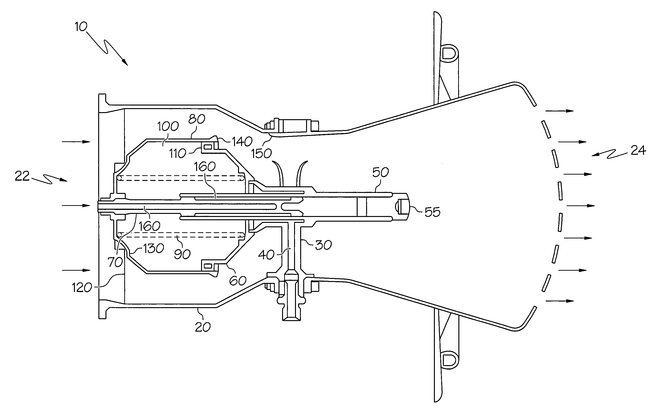
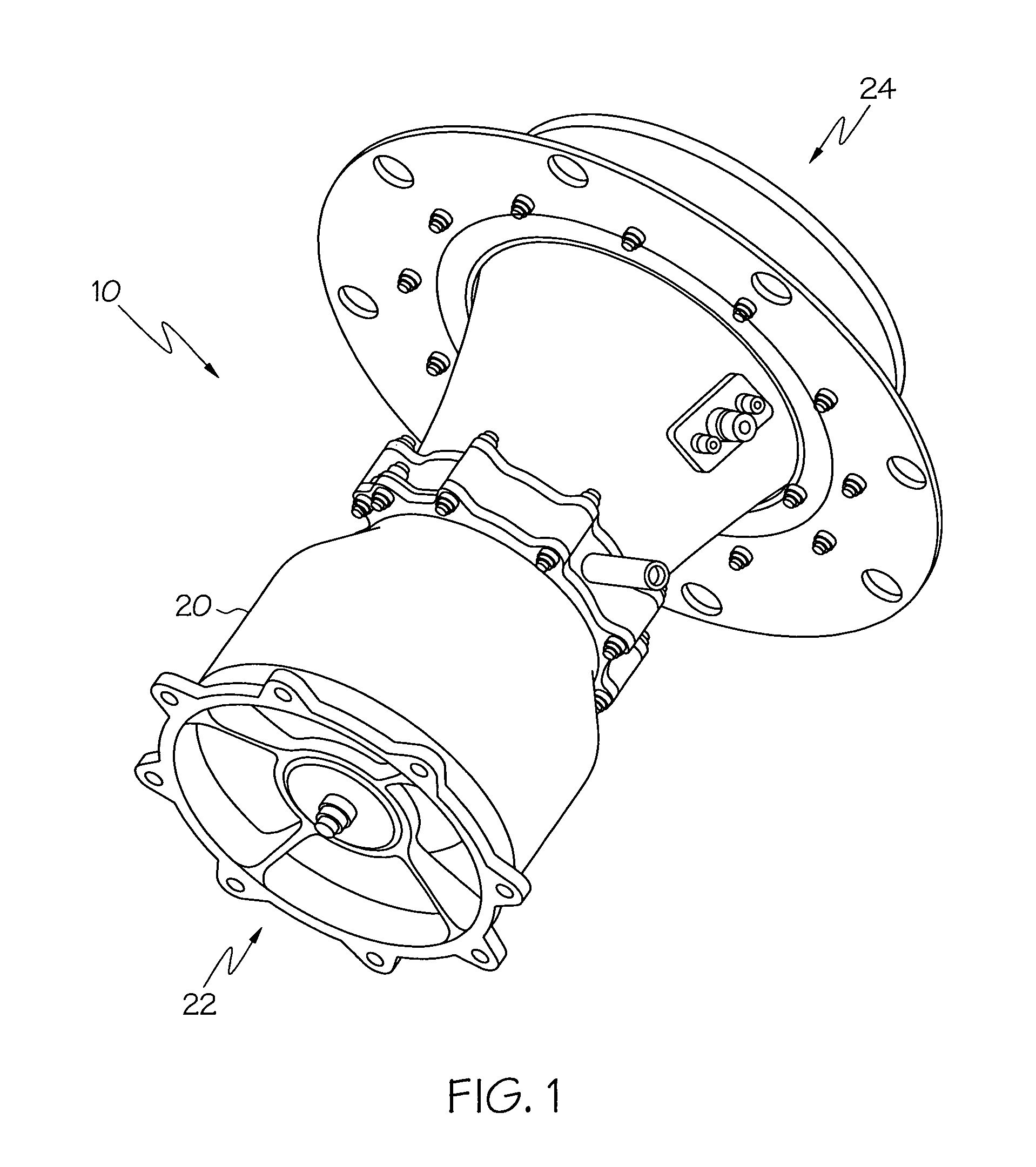
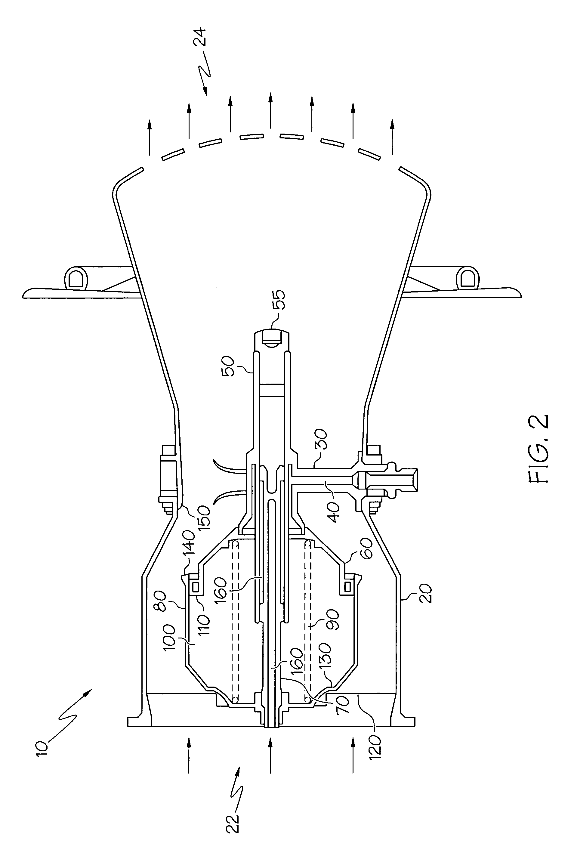
[0021]Referring now to FIG. 1 there is shown a schematic view of an intermediate pressure bleed valve. Bleed valve 10 includes main housing 20 defining an interior region and an exterior area. As is known in the art, main housing 20 may have on its exterior means to affix the bleed valve to the engine body. Flanged bolt holes with through bolts is one method by which the bleed valve may be attached to the engine. Main housing 20 may be a unitary or multi-component piece. For ease of manufacturing a multi component housing is preferred. Generally, the interior region of main housing 20 allows air to pass from opening 22 of main housing 20 through the interior region and passing out of outlet 24, when the valve is in the ...


PUM


Abstract

A bleed valve for use in a gas turbine engine is provided; the bleed valve may be used to relieve air pressure from a compressor stage of the engine. At normal pressure and when the engine is off, the bleed valve is in the open position. However once the engine starts, air pressure provided by the compressor closes the bleed valve. During engine operation, the bleed valve is opened to relieve air pressure by providing pressurized fluid, such as compressor air, to a valve chamber. The bleed valve is designed so that moveable parts of the valve, including contact seals and a sliding shaft, are protected by the valve structure from debris and contaminants carried in the engine's air stream.

Description

FIELD OF THE INVENTION[0001]The present invention relates to pressure control in gas turbine engines. In particular the present invention relates to bleed valves for use at compressor stages within gas turbine engines.BACKGROUND OF THE INVENTION[0002]Gas turbine engines such as those used in industrial, marine, vehicle, and aerojet applications, may include multiple stages of compressors. In a typical arrangement air is first drawn over a first compressor stage that elevates the air pressure to a desired level. The air, while passing in a generally axial direction through the engine, then crosses successive compressor stages that further raise the air pressure.[0003]It has been found that bleed valves can be used at various points on a gas turbine engine to assist in maintaining a desired level of air pressure within the engine. One area in a gas turbine engine where bleed valves are used is in the various compressor stages. A bleed valve or series of valves may be used to control u...

Claims


Application Information

Patent Timeline
Patent Type & Authority Patents(United States)
IPC IPC(8): F01B25/00F01D17/10F02C9/18F16K1/12
CPCF01D17/105F02C9/18F04D27/0215F04D27/023F05D2260/607F16K1/126Y02T50/60
Inventor D'ANGELO, GARYBANACH, TOMFRANCONI, ROBERTGIBB, JAMESGOODMAN, BOB
Owner HONEYWELL INT INC
Why Eureka
Try Eureka