
Touch type liquid-crystal display device and input detecting method

a liquid crystal display and touch-type technology, applied in the direction of static indicating devices, identification means, instruments, etc., can solve the problems of deteriorating display quality, glaring light, and large external light reflection in the face, and achieve excellent forming efficiency and excellent display quality.

Inactive Publication Date: 2006-01-03
NITTO DENKO CORP
View PDF20 Cites 85 Cited by
  • Summary
  • Abstract
  • Description
  • Claims
  • Application Information

AI Technical Summary

Benefits of technology

[0008]An object of the present invention is to develop a transmission type or reflection type liquid-crystal display device equipped with a touch panel in which glaring or lowering of contrast owing of reflection of external light is so little that the display device is excellent in display quality.
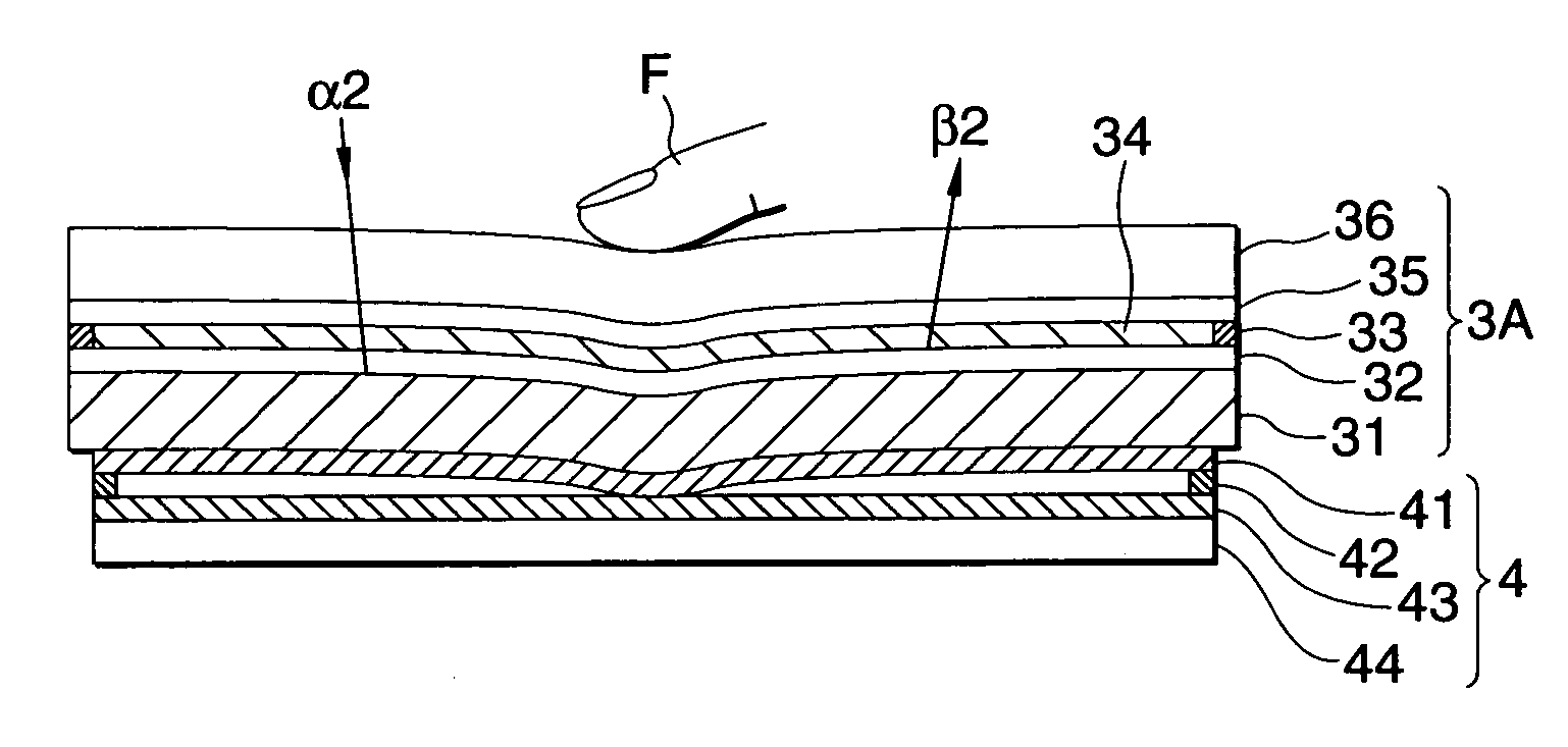
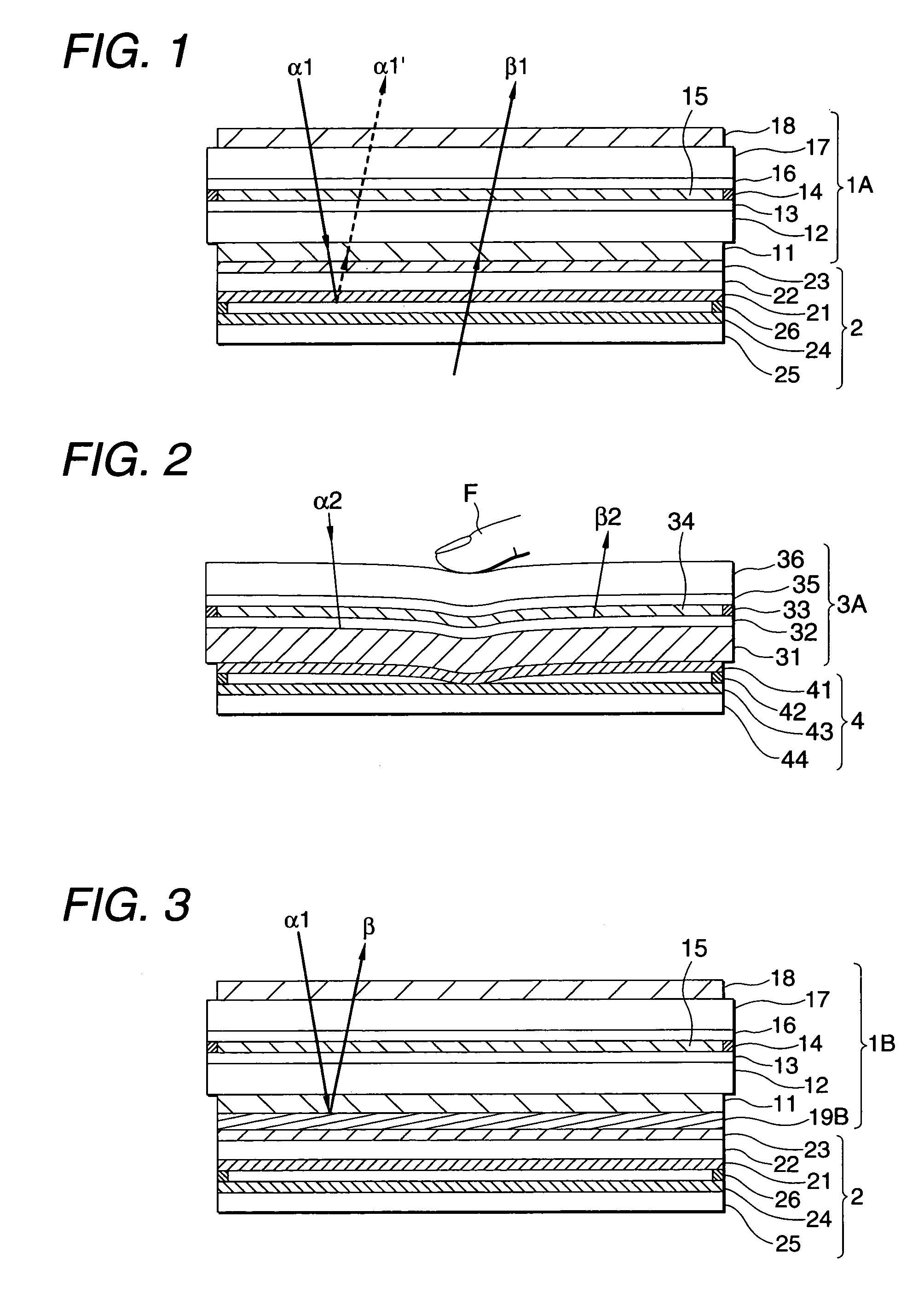
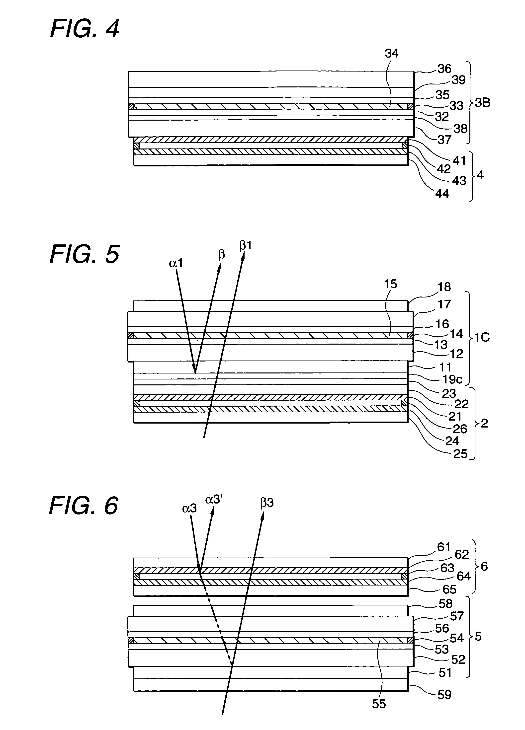
[0010]According to the present invention, the liquid-crystal display panel having flexibility can be bent by a pressing force to thereby make an input operation in the touch panel. In the condition that external light is attenuated by the liquid-crystal display panel, the external light enters the touch panel or is reflected by the light reflection layer. Hence, there is no or little reflection light generated in the touch panel, so that glaring or lowering of contrast owing to the reflection of external light hardly occurs. Hence, the liquid-crystal display device can be obtained as a transmission type or reflection type liquid-crystal display device equipped with a touch panel excellent in display quality. Incidentally, in the case of a transmission type liquid-crystal display device, light is attenuated by polarizers, a light absorbing layer, etc., in the liquid-crystal display panel so that the quantity of external light entering the touch panel can be generally reduced to be not larger than a half of that in the case of arrangement of the touch panel on the visual side. In the case of a reflection type liquid-crystal display device, external light entering the touch panel can be eliminated and the touch panel need not be made transparent, so that opaque electrodes excellent in forming efficiency, or the like, can be used in the touch panel.

Problems solved by technology

Increase of the number of interfaces in the arrangement of the touch panel on the visual side, however, brought interfacial reflection of a large amount of external light.
This caused glaring light.
Hence, there was a problem that contrast of display light in the liquid-crystal display panel was lowered so that display quality was deteriorated.
In the current circumstances, however, the anti-reflection effect is so poor that the effect of improving display equality has been never obtained correspondingly to increase in the number of production steps.

Method used


Image

  • Touch type liquid-crystal display device and input detecting method
  • Touch type liquid-crystal display device and input detecting method
  • Touch type liquid-crystal display device and input detecting method

Examples


example 1

[0043]Two planished plates were disposed and fixed into a mold through a spacer with a predetermined thickness. An alicyclic epoxy resin was injected into the mold and cured at 120° C. for 2 hours thus to form a resin plate 100 μm thick. The resin plate was cut into a predetermined size. Then, a plasma treatment was applied to the resin plate in an atmosphere of argon and a transparent electrode of indium-tin oxide (ITO) was formed on the resin plate by a sputtering method. Then, a polyvinyl alcohol solution was applied onto the resin plate with the transparent electrode by a spin coating method and a rubbing treatment was applied to the resulting dried film. Thus, a transparent resin substrate was obtained.

[0044]Then, two transparent resin substrates, one of which was obtained in the aforementioned manner and the other of which was obtained in the aforementioned manner except that the transparent electrode was further divided into two parts by etching, were disposed to be opposite ...

example 2

[0046]A transparent resin substrate was formed in the same manner as in Example 1. An ITO film was formed on one surface of the transparent resin substrate. On the other hand, a black substrate was formed as a mixture of a black pigment, and ITO films were formed on opposite surfaces of the black substrate. A rubbing treatment was applied to each of the two substrates. The two substrates were disposed to be opposite to each other through the electrode side so that the rubbing directions intersect each other perpendicularly while a gap adjusting material of spherical glass beads was disposed. Then, the two substrates were fixed by a sealing material. Incidentally, the transparent electrode in one of the two substrates was divided into two parts by etching in advance.

[0047]Then, a mixture of 10 parts by weight of trimethylpropane acrylate, 10 parts by weight of 2-hydroxyethyl acrylate, 25 parts by weight of acryl oligomer (M-1200, made by Toa Gosei Chemical Industry Co., Ltd.), 0.5 pa...

example 3

[0049]A normally white reflection type liquid-crystal display panel was obtained in the same manner as in Example 1 except that the polarizer provided on the back side opposite to the visual side was replaced by a polarizer (NPF HEG1425DU, made by Nitto Denko Corporation) having a plastic film of a surface irregularity structure and a light reflection sheet which is coated with aluminum by vapor deposition and which is bonded to the plastic film. A touch panel was provided to the reflection type liquid-crystal display panel to thereby obtain a touch type liquid-crystal display device. Hence, the light reflection sheet was positioned between the touch panel and the liquid-crystal cell.


PUM

PropertyMeasurementUnit
Forceaaaaaaaaaa
Flexibilityaaaaaaaaaa
Transmissionaaaaaaaaaa

Abstract

A touch type liquid-crystal display device has a liquid-crystal display panel having flexibility, a touch panel provided to adhere closely to a back side, opposite to a visual side, of the liquid-crystal display panel, and electrodes disposed to be opposite to each other through a gap. The electrodes are capable of coming into partial contact with each other by a pressing force to thereby detect an input position.

Description

BACKGROUND OF THE INVENTION[0001]1. Field of the Invention[0002]The present invention relates to an input position detection-style touch type liquid-crystal display device in which viewing blockade based on light reflected by a touch panel is suppressed so that the device is excellent in display quality.[0003]The present application is based on Japanese Patent Applications No. 2000-21310 and 2000-114817, which are incorporated herein by reference.[0004]2. Description of the Related Art[0005]Heretofore, as shown in FIG. 6, a transmission type liquid-crystal display device or a reflection type liquid-crystal display device is known as a touch type liquid-crystal display device equipped with a touch panel for detecting an input position. The transmission type liquid-crystal display device comprises a liquid-crystal display panel 5, and a touch panel 6. The liquid-crystal display panel 5 includes a pair of transparent substrates 52 and 57 provided with transparent electrodes 53 and 56 r...

Claims


Application Information

Patent Timeline
IPC IPC(8): G02F1/1335G02F1/13G02F1/133G02F1/1333G02F1/1334G06F3/041G09F9/00
CPCG02F1/13338G02F1/133305
Inventor UMEMOTO, SEIJINOGUCHI, TOMONORIKAMEYAMA, TADAYUKISHIMODAIRA, KIICHISUGAWARA, HIDEOANDOU, HIDEHIKO
Owner NITTO DENKO CORP
Learn More