
Methods and apparatus for reducing gas turbine engine emissions

Inactive Publication Date: 2006-01-10
GENERAL ELECTRIC CO
View PDF23 Cites 66 Cited by
  • Summary
  • Abstract
  • Description
  • Claims
  • Application Information

AI Technical Summary

Benefits of technology

[0005]In an exemplary embodiment, a gas turbine engine includes a combustor system to reduce an amount of nitrous oxide emissions formed by the gas turbine engine. The combustor system includes a combustor and a fuel and water delivery system. The combustor is a lean premix combustor including a plurality of premixers and is operable with a fuel / air mixture equivalence ratio less than one. The water delivery system supplies at least one of water or steam to the gas turbine engine such that water or steam is injected into the combustor.
[0006]During normal gas turbine engine operations, fuel is supplied proportionally with airflow to the combustor such that the combustor operates with a fuel / air mixture equivalence ratio less than one. As gas turbine engine operating speeds increase and additional fuel and air are supplied to the combustor, the water delivery sub-system supplies either water or steam to the combustor. The increase in combustion zone flame temperatures generated as a result of additional fuel being burned within the combustor is minimized with the water or steam supplied to the combustor. As a result, nitrous oxide emissions generated are reduced. Alternatively, the gas turbine engine may achieve an increased operating power level for a specified nitrous oxide emission level.

Problems solved by technology

Making modifications to a gas turbine engine in an effort to reduce nitrous oxide emissions often has an adverse effect on operating performance levels of the associated gas turbine engine.
Gas turbine engines include preset operating parameters and any such airflow increases are limited by the preset operating parameters including turbine nozzle cooling parameters.
Because such gas turbine engine modifications are labor-intensive and time-consuming, users are often limited to derating the operating power capability of the gas turbine engine and prevented from operating the gas turbine engine at full capacity.
Such derates do not limit an amount of nitrous oxide formed as the engine operates at full capacity, but instead limit the operating capacity of the gas turbine engine.

Method used


Image

  • Methods and apparatus for reducing gas turbine engine emissions
  • Methods and apparatus for reducing gas turbine engine emissions
  • Methods and apparatus for reducing gas turbine engine emissions

Examples


Embodiment Construction

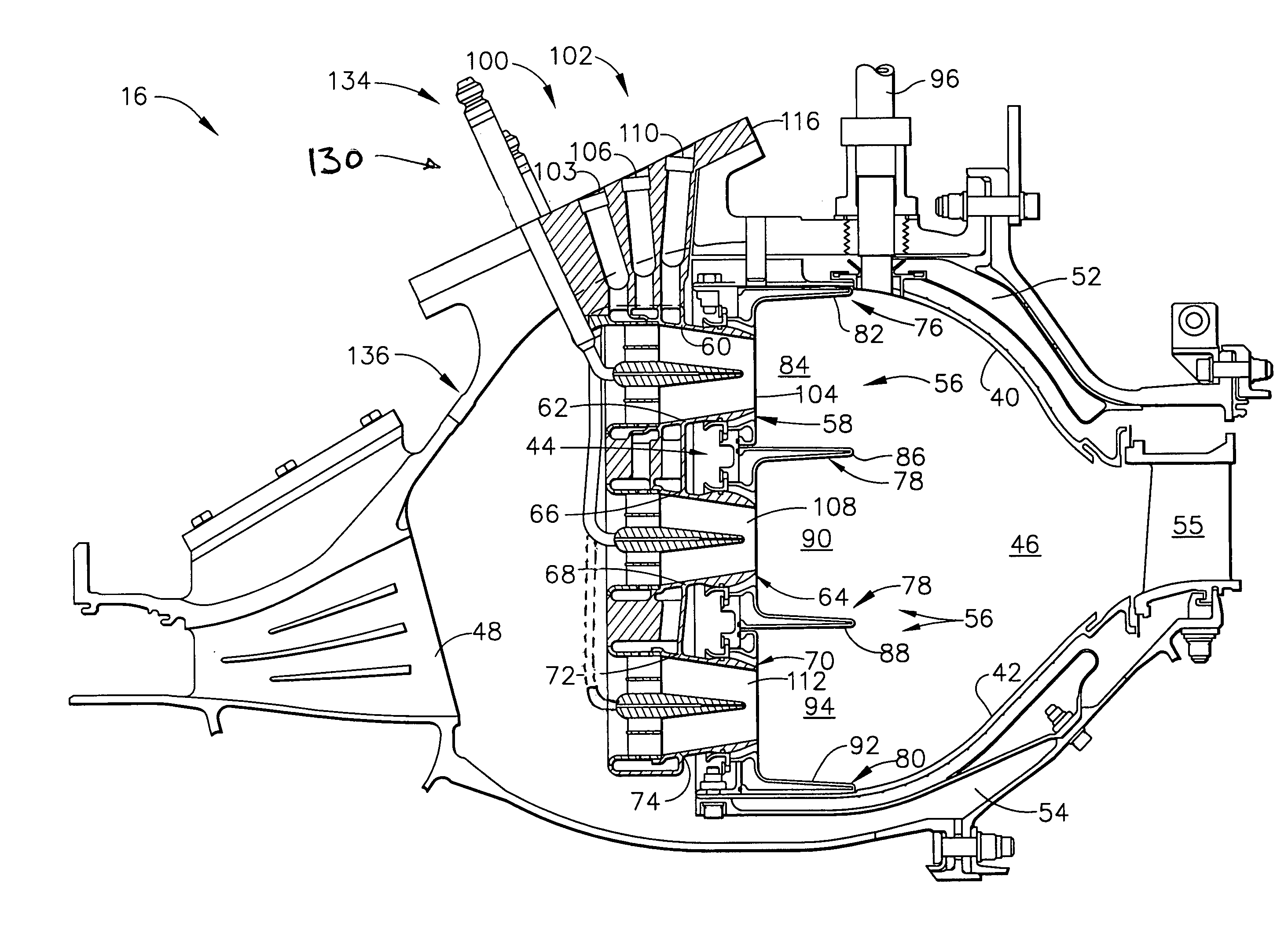
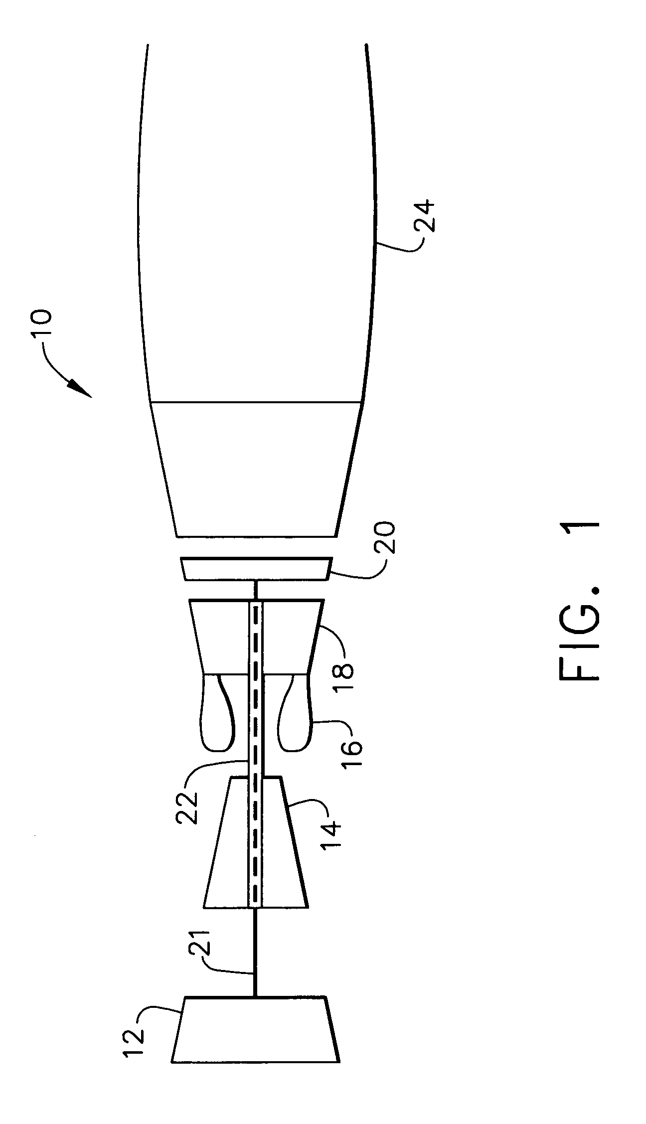
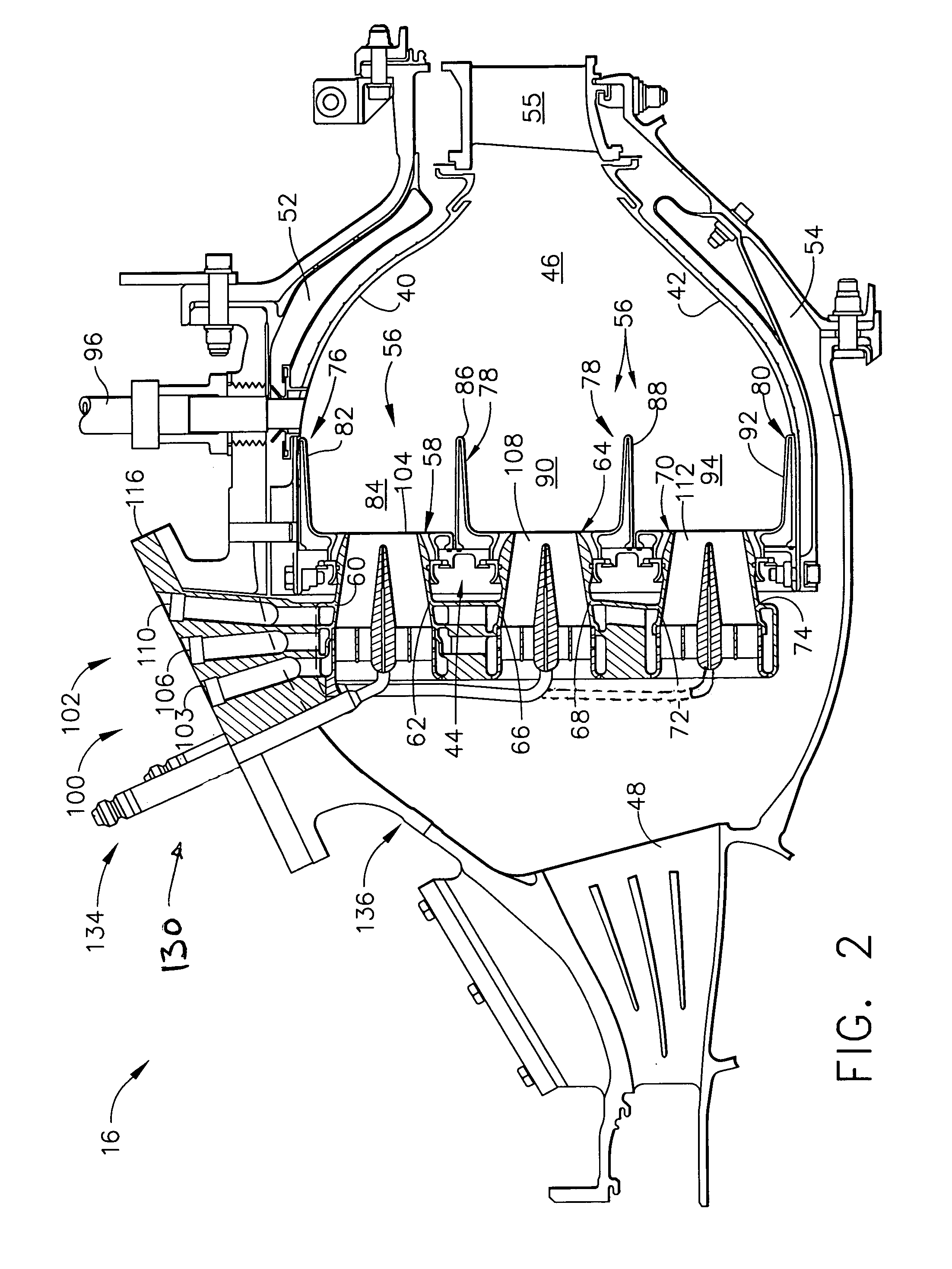
[0009]FIG. 1 is a schematic illustration of a gas turbine engine 10 including a low pressure compressor 12, a high pressure compressor 14, and a combustor 16. Engine 10 also includes a high pressure turbine 18 and a low pressure turbine 20. Combustor 16 is a lean premix combustor. Compressor 12 and turbine 20 are coupled by a first shaft 21, and compressor 14 and turbine 18 are coupled by a second shaft 22. A load (not shown) is also coupled to gas turbine engine 10 with first shaft 21. In one embodiment, gas turbine engine 10 is an LM6000 available from General Electric Aircraft Engines, Cincinnati, Ohio. Alternatively, gas turbine engine 10 is an LM 2500 available from General Electric Aircraft Engines, Cincinnati, Ohio.

[0010]In operation, air flows through low pressure compressor 12 and compressed air is supplied from low pressure compressor 12 to high pressure compressor 14. The highly compressed air is delivered to combustor 16. Airflow from combustor 16 drives turbines 18 and ...


PUM


Abstract

A gas turbine engine includes a combustor system including a lean premix combustor and a water delivery system. The combustor is operable with a fuel / air mixture equivalence ratio less than one and the water delivery system is configured to supply at least one of water or steam to the gas turbine engine such that either the water or the steam is injected into the combustor to control emissions generated by the combustor. As a result, nitrous oxide emissions for specified turbine operating power levels are lowered.

Description

BACKGROUND OF THE INVENTION[0001]This application relates generally to gas turbine engines and, more particularly, to combustors for gas turbine engine.[0002]Air pollution concerns worldwide have led to stricter emissions standards. These standards regulate the emission of oxides of nitrogen (NOx), unburned hydrocarbons (HC), and carbon monoxide (CO) generated as a result of gas turbine engine operation. In particular, nitrogen oxide is formed within a gas turbine engine as a result of high combustor flame temperatures. Making modifications to a gas turbine engine in an effort to reduce nitrous oxide emissions often has an adverse effect on operating performance levels of the associated gas turbine engine.[0003]In gas turbine engines, nitrous oxide emissions can be reduced by increasing airflow through the gas turbine combustor during operating conditions. Gas turbine engines include preset operating parameters and any such airflow increases are limited by the preset operating param...

Claims


Application Information

Patent Timeline
IPC IPC(8): F02C3/30F02C9/26F23R3/00F02C9/48F23L7/00F23R3/28F23R3/30
CPCF23L7/002F23R3/286F23L2900/07009
Inventor HOOK, RICHARD B.DAVIDSON, JOHN M.KRESS, ERIC J.SMITH, JR., JACK W.STEGMAIER, JAMES W.HEBERLING, PAUL V.PATTERSON, DAVID B.
Owner GENERAL ELECTRIC CO
Learn More