Cooling water pump device for outboard motor

a technology of pump device and outboard motor, which is applied in the direction of muscle operated starter, marine propulsion, vessel construction, etc., can solve the problems of increasing cost, poor mass productivity, and high material cost and processing cost, so as to reduce heat conduction, and prevent the resin pump case from melting

Active Publication Date: 2006-01-10
SUZUKI MOTOR CORP
View PDF14 Cites 60 Cited by
  • Summary
  • Abstract
  • Description
  • Claims
  • Application Information

AI Technical Summary

Benefits of technology

[0035]According to the invention of the above sixth feature, since ribs are formed in the interior surface of the pump case so as to create an air layer between the pump interior surface and the metal sleeve, frictional heat arising when the impeller frictionally rotates inside the sleeve can be prevented from transferring to the pump case by insulation and reduction of heat conduction owing to presence of the air layer. As a result it possible to reliably prevent the resin pump case from being heated by the frictional heat and hence prevent the resin pump case from melting.

Problems solved by technology

However, a pump case made of stainless steel suffers from various drawbacks: it is heavier than the that made of resin, causing a hindrance to lightening of the engine; and it is usually produced using the lost wax process, which is poor in mass productivity and needs high material cost and processing cost, resulting increase in cost.
However, the resin pump case tends to deform due to heat during the operation in the dry.
Further, for the case where outboard motors are used in seawater, saltwater may enter the interface between the pump case and the metal sleeve, forming salt buildup which may cause cracks in the case and deformation of the metal sleeve.
Use of an automatic sealant coater to deal with this results in cost increase.
And also, the sealant effectiveness will become lower due to heat and aging.
Further, when the metal sleeve is to be replaced, adhesion of sealant is hard to peel off, increasing the workload.
Moreover, when a new part is to be assembled, sealant is to be applied at a site in the local dealer, resulting in increase the number of steps and yet lack of reliability.

Method used


Image

  • Cooling water pump device for outboard motor
  • Cooling water pump device for outboard motor
  • Cooling water pump device for outboard motor

Examples


example 1

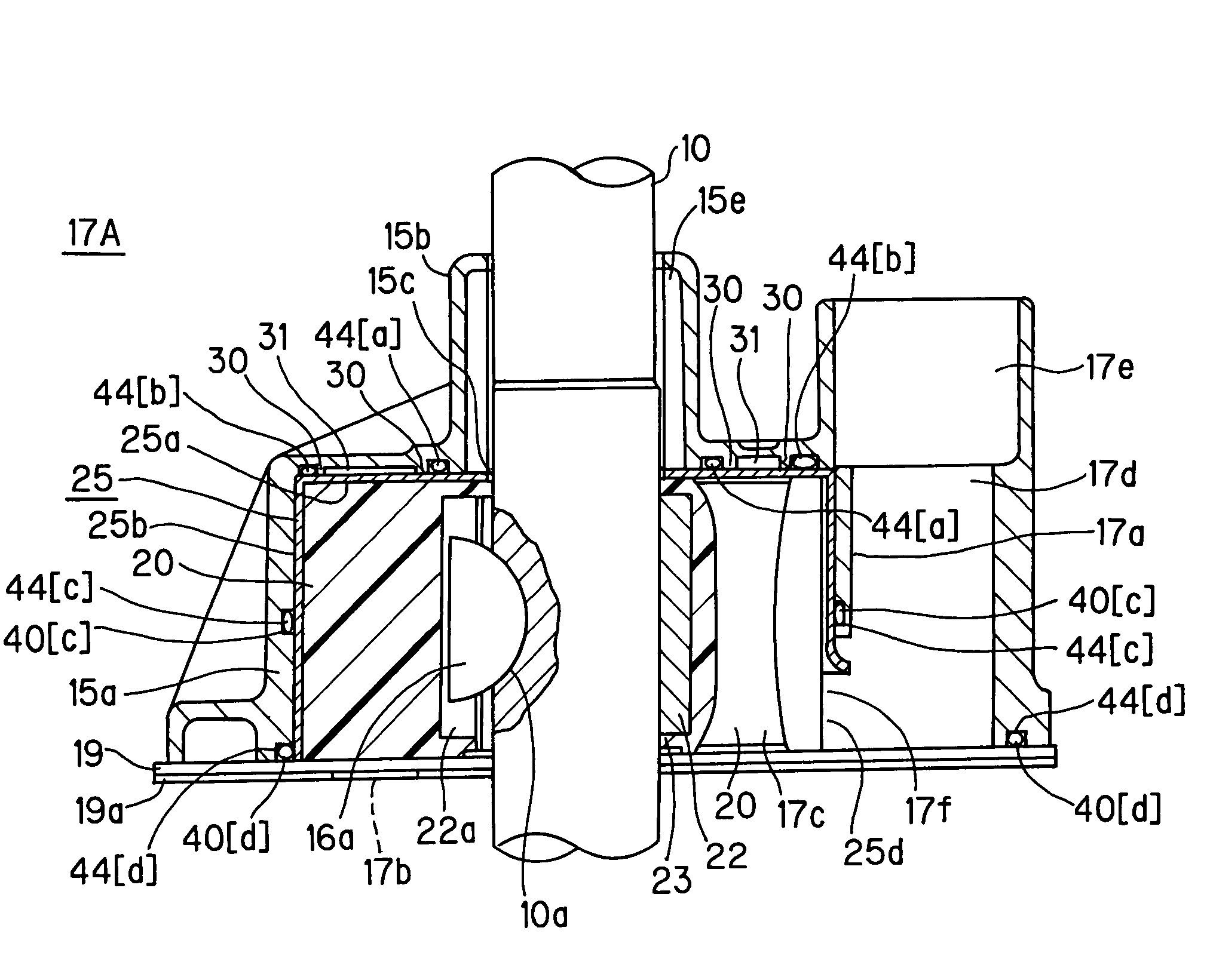
[0116]The sealing structure of example 1 is given in combination of annular seal elements denoted by 40[a], 40[b] and 40[d], as shown in FIGS. 8A and 8B. Specifically, this sealing structure is composed of an annular seal element 40[a] located close to insert hole 15c of driveshaft 10 in large-diametric cylinder 15a, an annular seal element 40 [b] located at a place away from the above element and close to the periphery of large-diametric cylinder 15a and an annular seal element 40[d] interposed between the rim of bottom opening 15d of pump case 15 and under-panel 19.

[0117]In FIGS. 8A and 8B, the sealed area (watertight area) from the annular seal elements is indicated by hatching 46. In FIGS. 8A and 8B, the broken line denotes the position of annular seal element 40[c].

[0118]With the above sealing structure of example 1, sealed area 46 is set up to extend between ceiling area of large-diametric cylinder 15a and the bottom 25a of sleeve 25, as shown in FIGS. 8A and 8B. In the conve...

example 2

[0119]The sealing structure of example 2 is given in combination of annular seal elements denoted by 40[a], 40[c] and 40[d], as shown in FIGS. 9A and 9B. Specifically, this sealing structure is composed of an annular seal element 40[a] located close to insert hole 15c of driveshaft 10 in large-diametric cylinder 15a, an annular seal element 40 [c] arranged opposing the side wall portion 25b of sleeve 25 and annularly passing along the upper edge of the cutout 25d of sleeve 25 and near and above ejection port 17f, and an annular seal element 40[d] interposed between the rim of bottom opening 15d of pump case 15 and under-panel 19.

[0120]In the above sealing structure of example 2, sealed area 46 shown in FIGS. 9A and 9B is made to extend up to the side wall portion of large-diametric cylinder 15a, though only the ceiling portion of large-diametric cylinder 15a can be sealed in the sealing structure of example 1. Thus the sealed area is enlarged.

[0121]Next, sealing structures of exampl...

example 3

[0123]The sealing structure of example 3 is configured, as shown in FIGS. 10A and 10B, so that the aforementioned annular seal elements are arranged at a place (40[a]) adjacent to insert hole 15c and at another place (40[b]) away from the former, both surrounding driveshaft insert hole 15c at the upper position of the pump case 15, and three joint seal elements (42[e] to 42[g]) extending in the radial direction of driveshaft 10 are provided to join the annular seal elements one to another. Further, an annular seal element 40[d] is interposed at the position between the rim of bottom opening 15d of pump case 15 and under-panel 19.

[0124]This sealing structure is given in combination of an annular seal element 40[a] located close to insert hole 15c of driveshaft 10 in large-diametric cylinder 15a, an annular seal element 40[b] located at a place more distant from insert hole 15c and close to the periphery of large-diametric cylinder 15a, joint seal elements 42[e] to 42[g] arranged radi...


PUM


Abstract

A cooling water pump device for drawing cooling water from bottom of a pump case and pumping it toward an engine located above includes: a multiple number of annular seal elements surrounding the driveshaft for keeping the interface between the inner peripheral surface of a resin pump case and a metal sleeve watertight, arranged between the inner peripheral surface of the resin pump case and the metal sleeve, at plural positions vertically apart with respect to the axial direction of the driveshaft.

Description

BACKGROUND OF THE INVENTION[0001](1) Field of the Invention[0002]The present invention relates to a cooling water pump device for pumping cooling water toward an engine of an outboard motor that includes a hollow driveshaft housing under the engine and a driving shaft vertically mounted in the driveshaft housing for transmitting the drive force of the crankshaft of the engine to a screw.[0003](2) Description of the Prior Art[0004]The outboard motor engine is cooled by taking in seawater or river water through, for example, a water filter in the lower case (or gear case) and forwarding the intake seawater or river water to the water jacket of the engine as cooling water.[0005]In general, an outboard motor is equipped with a cooling water pump device for sending (pumping up) cooling water for engine cooling.[0006]Specifically, an outboard motor is provided under its engine with a driveshaft housing that incorporates a driving shaft mounted vertically for transmitting the drive force o...

Claims


Application Information

Patent Timeline
Patent Type & Authority Patents(United States)
IPC IPC(8): B63H21/38B63H20/28F01P3/20F01P5/10F01P5/12F04C2/344F04C5/00F04C13/00F04C15/00F04C29/00F04D29/42
CPCF01P3/202F01P5/12F04C15/0038F04C5/00B63B2770/00F05C2253/20F05C2201/046B63H20/28
Inventor SATOH, TAKUYANAGANUMA, KOJI
Owner SUZUKI MOTOR CORP
Why Eureka
Try Eureka