Electrolyte copper foil having carrier foil, manufacturing method thereof, and layered plate using the electrolyte copper foil having carrier foil

a technology carrier foil, which is applied in the field of manufacturing method thereof, and layered plate using electrolyte copper foil having carrier foil, can solve the problems of wire breaking, copper foil wrinkle generation becomes a serious problem, and conventional peelable foil, however, is extremely unstable, and achieves the effect of easy peeling

Inactive Publication Date: 2006-01-10
MITSUI MINING & SMELTING CO LTD
View PDF6 Cites 7 Cited by
  • Summary
  • Abstract
  • Description
  • Claims
  • Application Information

AI Technical Summary

Benefits of technology

[0022]Consequently, the inventors according to the present invention, as a result of diligent study, arrived at the development of an electrodeposited copper foil with carrier foil that is a peelable electrodeposited copper foil with carrier foil, and in which the adhesive interface layer can be maintained in a sound state even under application of high temperatures exceeding 200° C., and furthermore, the peel strength between the carrier foil layer and the copper foil layer can be stabilized to a low level and the carrier foil can easily be peeled. Now, the invention will be described.

Problems solved by technology

In this connection, if wrinkles are present on the copper foils, cracks are generated in the wrinkled portions in the copper foils, which sometimes causes such inconveniences that resin exudes from the prepregs, and wiring breaking in formation circuits occurs in the printed wiring board manufacturing process that is an etching process to be conducted subsequently.
Wrinkle generation in copper foils becomes a serious problem as the copper foils become thinner.
The conventional peelable foil, however, is extremely unstable, after pressing, in the values of the peel strength of the carrier foil, and the satisfactory range of peel strength is generally assumed to fall in the range from 50 to 300 gf / cm.
On one hand, in extreme cases, it transpires that the carrier foil cannot be peeled and there has been a drawback that it is difficult to obtain targeted peel strengths.
The drawback has been the most serious obstruction when the electrodeposited copper foil with carrier foil widely prevails to be used in general purposes.
The electrochemical methods, however, find difficulty in extremely small quantity control of electrolytic deposition amount, and accordingly inferior to other technical methods in reproducibility.
Furthermore, because the necessary electrolytic deposition amount boundary for the bifurcation between the peelable foil and the etchable foil is, in other words, the small difference in the metal amount present in the adhesive interface layer, it is conceivable that it is difficult to bring forth the stable performance.
This rather operates toward enhancing the adhesive strength, and is possibly part of the reason that the peel strength becomes unstable.
Consideration of the above described matters leads to an anticipation that the use of conventional peelable electrodeposited copper foils with carrier foil will become more and more difficult.
On one hand, in connection with the etchable foil, dedicated etching equipment is needed, and the temporal cost required for etching tends to be high.
Consequently, the use of conventional etchable electrodeposited copper foils with carrier foil results in boosting up the overall manufacture cost, and accordingly there has been a drawback that the conventional etchable foils cannot easily be used for an extremely wide range of applications.
The electrodeposited copper foil with carrier foil, provided with an organic adhesive interface layer, however, is given a relatively low heat resistance temperature for the organic material constituting the organic adhesive interface layer, and the heat resistance temperature of the organic material generally usable for forming the organic adhesive interface is generally limited to the order of 200° C. Therefore, under the existing circumstances, it has been difficult to use organic material for manufacturing Teflon substrates, polyimide substrates and the like, all requiring the press processing at the temperatures higher than the above mentioned limit.
Decomposition of the organic material constituting the organic adhesive interface layer by heating causes the mutual diffusion between the carrier foil and the electrodeposited copper foil, preventing smooth peeling, which has made impossible the use of the electrodeposited copper foil with carrier foil for the purpose of applications expected by nature thereto.
Incidentally, independent use of a metal oxide layer causes the following drawback constituting an obstruction that prevents pursuing the mass productivity involving finished products and improving the production yield.
That is, when the thickness of the metal oxide layer exceeds a certain thickness, the peel strength between the carrier foil layer and the copper foil layer is increased, and additionally the peel strength comes to lack stability, and accordingly it becomes difficult to guarantee the quality of peel strength between the carrier foil layer and the copper foil layer.

Method used


Image

  • Electrolyte copper foil having carrier foil, manufacturing method thereof, and layered plate using the electrolyte copper foil having carrier foil
  • Electrolyte copper foil having carrier foil, manufacturing method thereof, and layered plate using the electrolyte copper foil having carrier foil
  • Electrolyte copper foil having carrier foil, manufacturing method thereof, and layered plate using the electrolyte copper foil having carrier foil

Examples


example 1

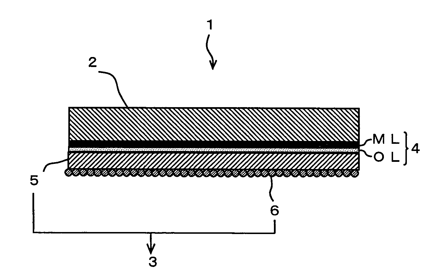
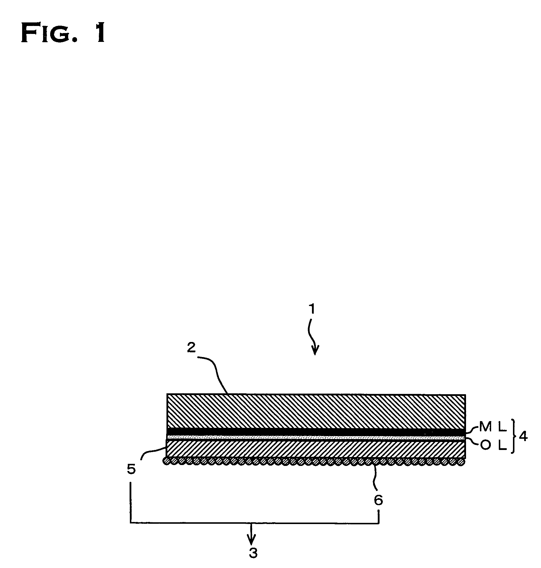
[0075]As for the present example, the results are described which are involved in the manufacture of the electrodeposited copper foil with carrier foil 1 shown in FIG. 1. Here, an electrodeposited copper foil of 35 μm in thickness, classified as grade 3, was used for the carrier foil 2, and an electrodeposited copper foil layer 3 of 5 μm in thickness was formed on the glossy surface of 0.21 μm in average roughness (Ra). In what follows, following the order of the individual processes, production conditions are described. Incidentally, in the processes described below in which the electrolysis method was used, a stainless plate was used for the anode electrode unless the materials are particularly specified.

[0076]At the beginning, the carrier foil 2 was made to get into the acid washing process. In the acid washing process, the inside of an acid washing vessel was filled with a diluted sulfuric acid solution of 150 g / l in concentration and of 30° C. in solution temperature; the carri...

example 2

[0089]As for the present example, the results are described which are involved in the manufacture of the double-sided electrodeposited copper foil with carrier foil 7 shown in FIG. 3. Here, a low-profile electrodeposited copper foil of 70 μm in thickness, classified as grade 3, was used for the carrier foil 2, and an electrodeposited copper foil layer 3 of 5 μm in thickness was formed on each of the glossy surface of 0.24 μm in average roughness (Ra) and the nodular surface of 0.82 μm in average roughness (Ra). In what follows, instead of describing the production conditions following the order of the individual processes, only the difference from those in Example 1 will be described, because the production conditions applied in the individual processes are fundamentally, exactly the same as those in Example 1.

[0090]The differences form Example 1 are as follows: in Example 1, an anode electrode was arranged on the side, except for the passivation process, but it is necessary to arra...


PUM

PropertyMeasurementUnit
thickaaaaaaaaaa
thickaaaaaaaaaa
thicknessaaaaaaaaaa

Abstract

An object is the provision of a peelable electrodeposited copper foil with carrier foil that stabilizes the peel strength between the carrier foil and the electrodeposited copper foil layer even when used in manufacture of the printed wiring boards that requires pressing at the temperatures of 200° C. or higher. For the purpose of achieving the object, the electrodeposited copper foil with carrier foil 1, which includes an adhesive interface layer 4 arranged on one face of the carrier foil 2 and an electrodeposited copper foil layer 3 arranged on the adhesive interface layer 4, characterized in that the adhesive interface layer 4 is composed of a metal oxide layer ML and an organic material layer OL, and the like are used.

Description

CROSS REFERENCE TO RELATED APPLICATION[0001]This application is a 35 USC § 371 National Phase Entry Application from PCT / JP02 / 13005, filed Dec. 12, 2002, and designating the U.S.TECHNICAL FIELD[0002]The present invention relates to electrodeposited copper foil with carrier foil, a manufacture method of the electrodeposited copper foil with carrier foil, a laminate utilizing the electrodeposited copper foil with carrier foil, and the like.BACKGROUND ART[0003]Conventionally, electrodeposited copper foil with carrier foil has been used as basic material for manufacturing printed wiring boards which are widely used in the fields of electric and electronic industries. In general, electrodeposited copper foils are bonded to glass-epoxy substrates, phenolic substrates, and insulating substrates made of polymers including polyimide, by means of hot pressing, to be utilized for manufacture of printed wiring boards as copper clad laminates.[0004]In the hot pressing, copper clad laminates are ...

Claims


Application Information

Patent Timeline
Patent Type & Authority Patents(United States)
IPC IPC(8): B32B15/04C25D3/38B32B9/00B32B7/06B32B15/08B32B15/20C25D1/04H05K3/02
CPCB32B7/06B32B15/08B32B15/20C25D1/04H05K3/025Y10T428/12903Y10S428/938Y10S428/935Y10S428/926Y10T428/265Y10T428/31678B32B15/04
Inventor SUGIMOTO, AKIKOYOSHIOKA, JUNSHIDOBASHI, MAKOTO
Owner MITSUI MINING & SMELTING CO LTD
Why Eureka
Try Eureka