Apparatus and method for retaining mirror, and mirror exchange method

a mirror and apparatus technology, applied in the field of optical systems and exposure apparatuses, can solve the problems of reducing the reflectance of an optical element, lithography using ultraviolet light having the limit, contamination, damage, etc., and achieves the effects of shortening the exchange time, facilitating the exchange of a mirror, and maintaining initial positioning accuracy

Inactive Publication Date: 2006-01-10
CANON KK
View PDF10 Cites 4 Cited by
  • Summary
  • Abstract
  • Description
  • Claims
  • Application Information

AI Technical Summary

Benefits of technology

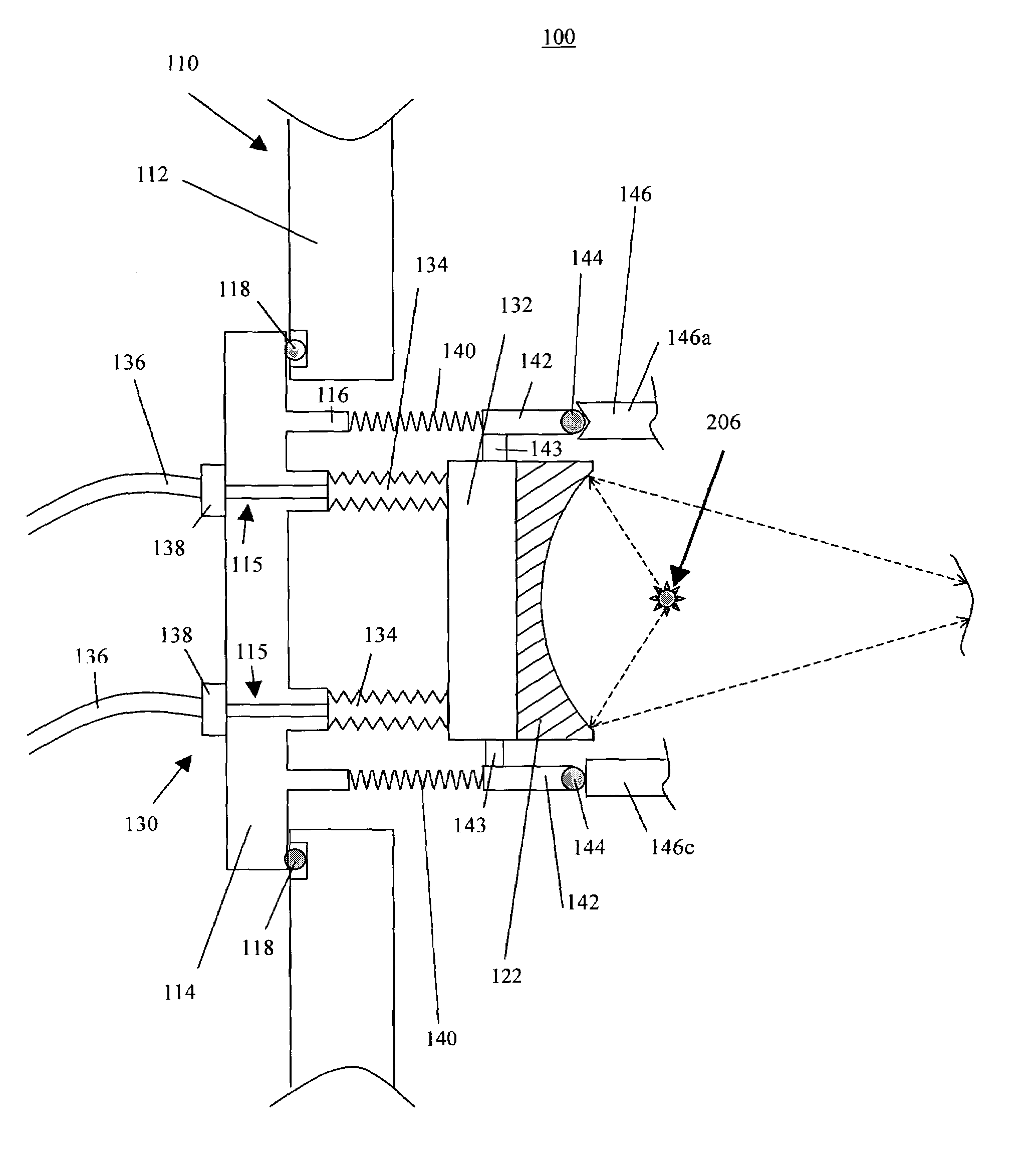
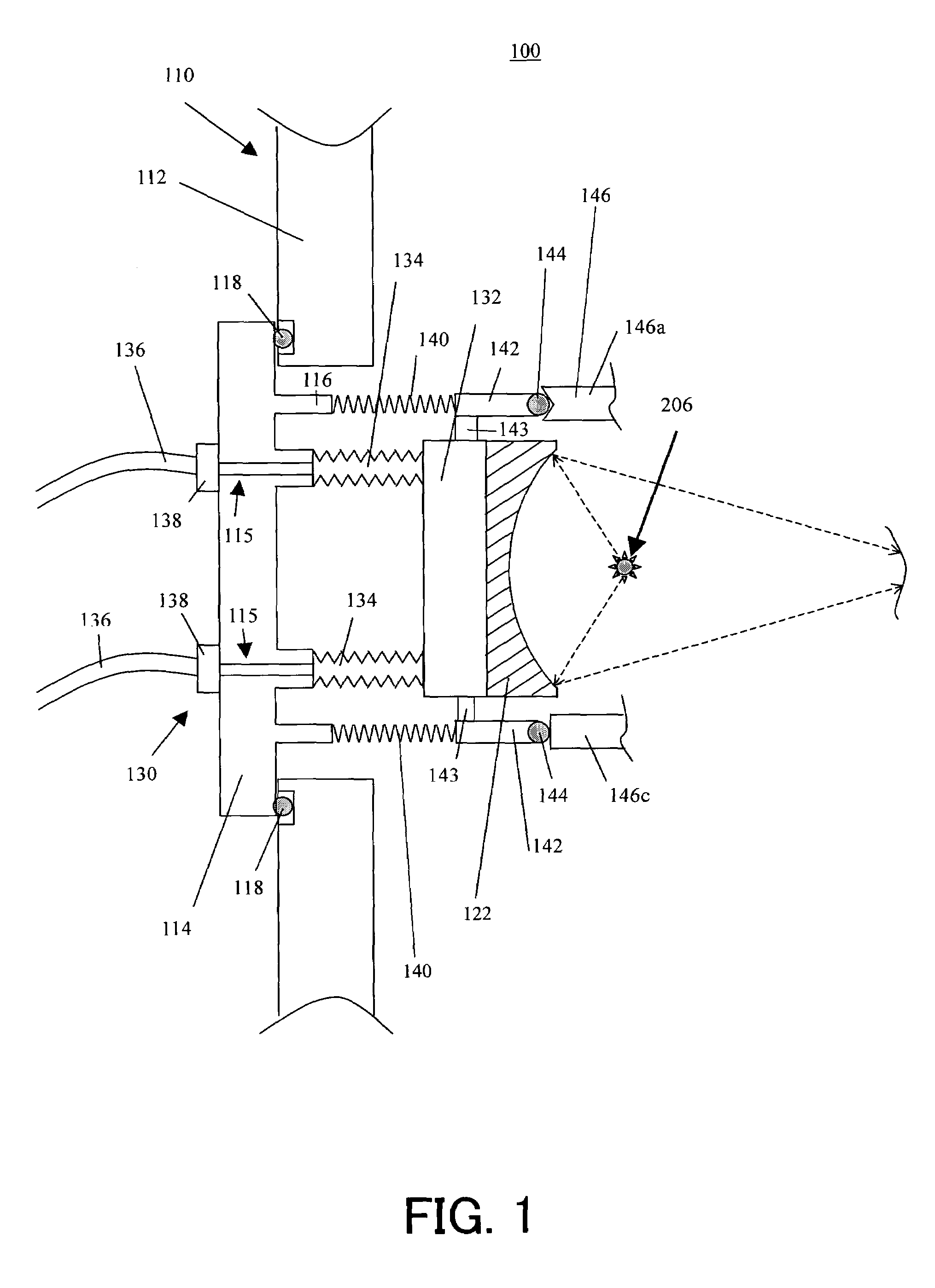
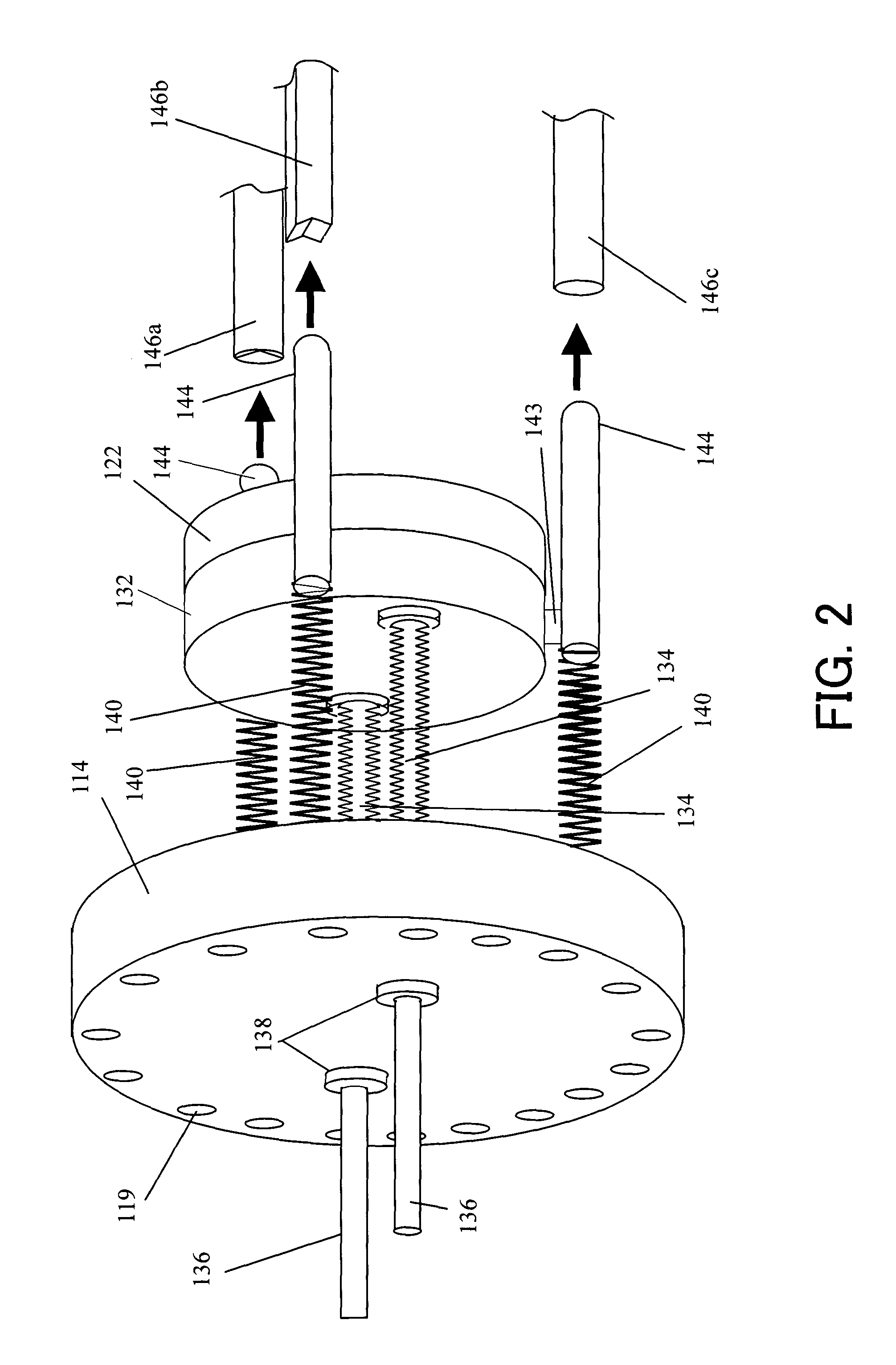
[0011]Accordingly, it is an exemplary object of the present invention to provide a mirror retainer, a mirror retaining method, a mirror exchange method, an exposure apparatus having the mirror retainer, and a device fabrication method that utilizes this exposure apparatus, which may facilitate an exchange of a mirror in an illumination optical system, maintain initial positioning accuracy, and shorten an exchange time.

Problems solved by technology

However, the lithography using the UV light has the limit to satisfy rapidly promoting fine processing of a semiconductor device, and a reduction projection exposure apparatus using EUV light with a wavelength of about 10 to 15 nm much shorter than that of the ultraviolet has been developed to efficiently transfer a very fine circuit pattern of 0.1 μm or less.
The laser plasma light source generates not only the EUV light, but also flying particles called debris, which causes contamination, damages and lowered reflectance of an optical element.
While some methods have been disclosed, for example, in Japanese Patent Application Publication No. 2000-349009, which prevent debris from reaching an optical element from the target, there has not been proposed a method for effectively preventing debris from reaching the first stage mirror, particularly close to the target, in the illumination optical system.
As a result, the debris adheres to a surface on the first mirror and lowers its reflectance over exposure time.
Thus, the conventional exchange of the mirror 4 requires a large maintenance space in the exposure apparatus and a long maintenance time, disadvantageously lowering exposure throughput and contaminating mirrors, such as an illumination optical system, and the chamber 1 due to a long opening time of the vacuum chamber 1.
This method may shorten an exchange time, because when the mirror is attached to a vacuum chamber, a mirror itself is simultaneously positioned.
However, actually, the vacuum chamber is likely to deform and the mirror also undesirably deforms along with a deformation of a wall surface of the vacuum chamber after the mirror is positioned by attaching it to the chamber.

Method used


Image

  • Apparatus and method for retaining mirror, and mirror exchange method
  • Apparatus and method for retaining mirror, and mirror exchange method
  • Apparatus and method for retaining mirror, and mirror exchange method

Examples


Embodiment Construction

[0031]A description will now be given of an exemplary exposure apparatus 100 of one embodiment according to the present invention, with reference to accompanying drawings. In each figure, the same reference numeral denotes the same element. FIG. 5 is a schematic plane view of the exposure apparatus 100. The exposure apparatus 100 is an exposure apparatus that uses EUV light (e.g., with a wavelength of 13.4 nm) as exposure light for step-and-scan exposure.

[0032]Referring to FIG. 1, the exposure apparatus includes a vacuum chamber 110, an illumination optical system 120, a catoptric reticle or mask 150, an alignment optical system 160, a projection optical system 170, a reticle stage 154, a wafer stage 184, an EUV light source 200, and accommodates the illumination optical system 120 to the wafer stage 180 in the vacuum chamber 110.

[0033]The EUV light source 200 uses, for example, a laser plasma light source. The laser plasma light source irradiates a highly intensified pulse laser be...


PUM

PropertyMeasurementUnit
wavelengthaaaaaaaaaa

Abstract

A mirror retainer for retaining a mirror accommodated in a chamber that has a wall and a lid openably provided on the wall, and generates a reduced pressure environment, includes an elastic member for connecting the mirror elastically to the lid.

Description

[0001]This application claims a benefit of foreign priority based on Japanese Patent Application No. 2002-266094, filed on Sep. 11, 2002, which is hereby incorporated by reference herein in its entirety as if fully set forth herein.BACKGROUND OF THE INVENTION[0002]The present invention relates generally to optical systems and exposure apparatuses, and more particularly to a method and apparatus for retaining a mirror used in an exposure apparatus. The present invention is suitable, for example, for an illumination optical system and projection exposure apparatus using an extreme ultraviolet (“EUV”) region having a wavelength of 200 nm to 10 nm or an X-ray region.[0003]Reduction projection exposures using ultraviolet have been conventionally employed to manufacture such a fine semiconductor device as a semiconductor memory and a logic circuit in photolithography technology. The critical dimension to be transferred by the reduction projection exposure is proportionate to a wavelength ...

Claims


Application Information

Patent Timeline
Patent Type & Authority Patents(United States)
IPC IPC(8): G03B27/42G02B5/08G02B7/00G02B7/18G02B7/182G02B17/06G03F7/20H01L21/027
CPCG02B7/1815G03F7/70891G03F7/70825G02B7/182
Inventor MIYACHI, TAKESHIMIYAKE, AKIRA
Owner CANON KK
Why Eureka
Try Eureka