
Method and apparatus for baseband transmission between a top floor unit and an outdoor unit in a terminal for a wireless metropolitan area network

Inactive Publication Date: 2006-01-10
SPARKMOTION
View PDF34 Cites 38 Cited by
  • Summary
  • Abstract
  • Description
  • Claims
  • Application Information

AI Technical Summary

Benefits of technology

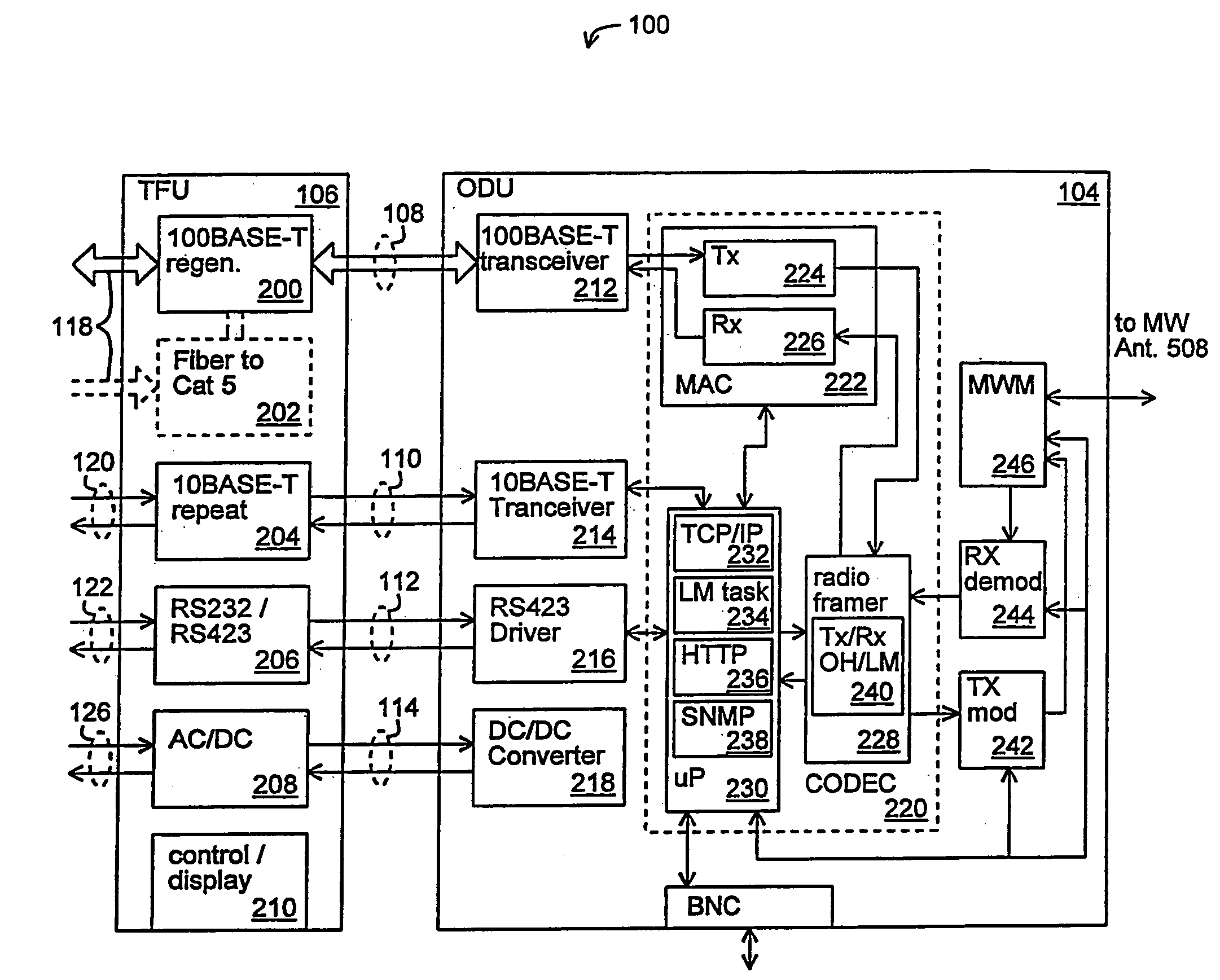
[0016]This technique has an advantage in that relatively inexpensive twisted pair cabling can be utilized for communicating the data packets between the top floor unit and the outdoor unit. Another advantage of this technique is that the top floor unit does not require relatively expensive components for modulating the data packets onto an intermediate frequency carrier signal. Rather, up-conversion is performed entirely in the outdoor unit.

Problems solved by technology

As such, the rate at which information can be communicated over these telephone links is limited.
As computers and computer applications become more sophisticated, however, they tend to generate and process increasingly large amounts of data to be communicated.
For example, the communication of computer graphics generally requires a large amount of bandwidth relative to voice communication.
Thus, the telephone link can become a data communication bottleneck.
Environmental precipitation causes a severe attenuation of the transmitted signal.
In addition, wireless links, especially those operated at high power levels, can cause interference with other wireless links operating in the same geographical area.
Thus, the wireless link can become a data communication bottleneck.
This arrangement has a disadvantage in that the required coaxial cabling is relatively expensive in comparison to other types of cables.
In addition, the IF converter increases the cost of the equipment required to be located inside of the building.

Method used


Image

  • Method and apparatus for baseband transmission between a top floor unit and an outdoor unit in a terminal for a wireless metropolitan area network
  • Method and apparatus for baseband transmission between a top floor unit and an outdoor unit in a terminal for a wireless metropolitan area network
  • Method and apparatus for baseband transmission between a top floor unit and an outdoor unit in a terminal for a wireless metropolitan area network

Examples


Embodiment Construction

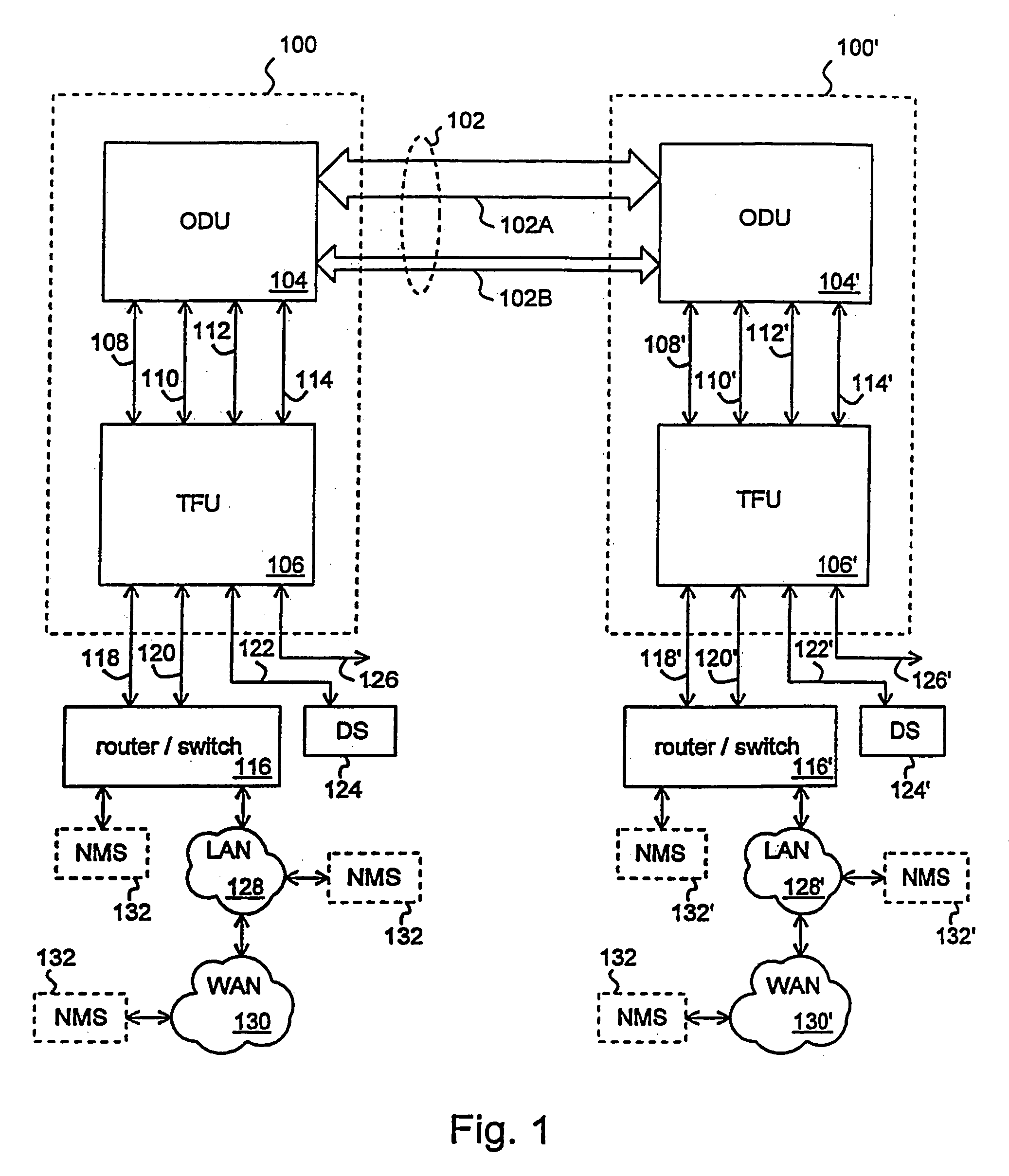
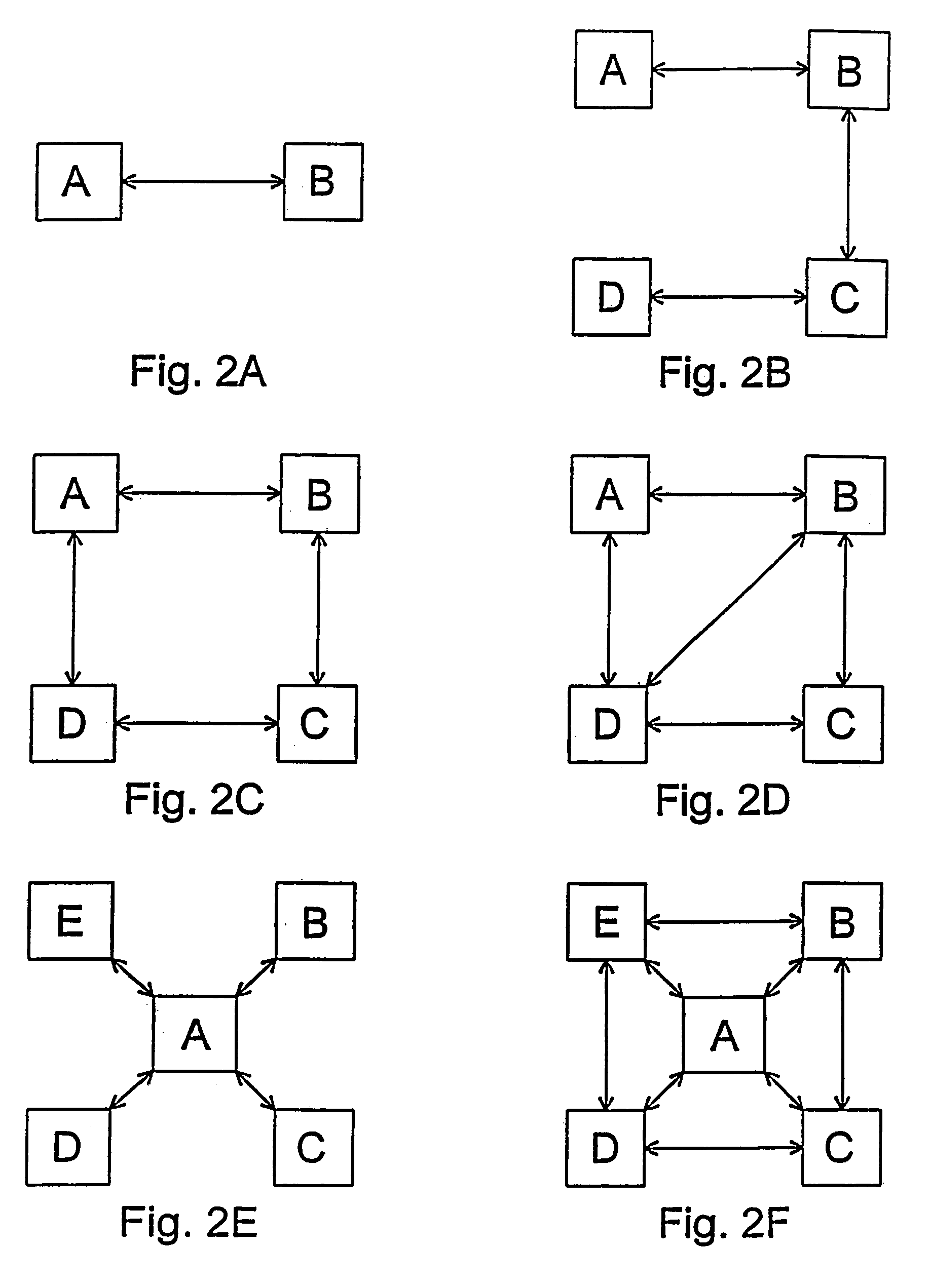
[0040]FIG. 1 illustrates a schematic block diagram of a pair of wireless terminals 100, 100′ which communicate with each other via a bi-directional wireless communication link 102 in accordance with the present invention. Though a single wireless communication link 102 is illustrated, it will be apparent that a network of wireless communication links can interconnect a plurality of wireless terminals, thereby forming a wireless metropolitan area network (MAN) in accordance with the present invention. FIGS. 2A–F illustrate representative MAN topologies which interconnect wireless nodes A–E with wireless links according to the present invention. Each of the nodes A–E can include a wireless terminal identical to the terminal 100 or 100′ illustrated in FIG. 1 for terminating each wireless link. It will be apparent that other MAN topologies can be implemented and that one or more of the nodes A–E can be coupled to one or more other types of networks.

[0041]Due to availability of portions ...


PUM


Abstract

A method and apparatus for baseband transmission between a top floor unit and an outdoor unit in a terminal for a wireless metropolitan area network. A terminal for a wireless link in a metropolitan area network includes an extender device (e.g. a top floor unit) for receiving data packets from a computer network coupled to the extender device and for forwarding the data packets, and a broadcast device (e.g. an outdoor unit) coupled to the extender device for receiving the data packets from the extender device according to baseband transmission and having a wireless transceiver for communicating the data packets over the wireless link. The terminal can include a cable coupled between the extender device and the broadcast device wherein the cable comprises a twisted pair of conductors for providing the data packets from the extender device to the broadcast device. The twisted pair of conductors can be a Category 5 twisted pair of conductors. Thee broadcast device can include a microwave antenna coupled to the wireless transceiver; and a housing coupled to the microwave antenna for enclosing the wireless transceiver.

Description

[0001]This is a Continuation-in-Part of application Ser. No. 08 / 950,028, filed Oct. 14, 1997, the contents of which are hereby incorporated by reference. This application claims the benefit of U.S. Provisional Application Ser. No. 60 / 086,459, entitled, “Method and Apparatus for Wireless Communication of Fast Ethernet Data Packets,” filed May 22, 1998.FIELD OF THE INVENTION[0002]The invention relates to a terminal for a wireless network for a metropolitan area wherein the terminal includes a top floor unit (extender device) and an outdoor unit (broadcast device). More particularly, the invention relates to a terminal for communicating Fast Ethernet data packets between the top floor unit and the outdoor unit via baseband transmission.BACKGROUND OF THE INVENTION[0003]Computers utilized in modern office environments are typically coupled to a local area network (LAN). The LAN allow users of the computers to share common resources, such as a common printer included in the network, and a...

Claims


Application Information

Patent Timeline
IPC IPC(8): H04B7/00H04L12/28H04B7/14H04L25/00
CPCH04L5/14H04L5/16H04L12/24H04L41/00Y10S370/902H04L41/046H04L41/22Y10S370/913H04L41/0213
Inventor NATTIV, MOSHEHUEN, TATNGOC, THO LETREADAWAY, KIRKHAMILTON, MIKE
Owner SPARKMOTION
Learn More