Semiconductor micro-resonator for monitoring an optical device

a micro-resonator and semiconductor technology, applied in the field of micro-resonators, can solve problems such as feedback into the laser or increased nois

Inactive Publication Date: 2006-01-10
BROADCOM INT PTE LTD
View PDF18 Cites 11 Cited by
  • Summary
  • Abstract
  • Description
  • Claims
  • Application Information

AI Technical Summary

Benefits of technology

[0014]According to another aspect of the invention, the device includes a plurality of micro-resonators, each having a respectively different resonant wavelength so that light having multiple different wavelengths may be detected.

Problems solved by technology

Splicing optical fibers to the output fiber to tap the light may cause undesirable power loss or scattering of light that may result in increased noise or feedback into the laser.

Method used


Image

  • Semiconductor micro-resonator for monitoring an optical device
  • Semiconductor micro-resonator for monitoring an optical device
  • Semiconductor micro-resonator for monitoring an optical device

Examples


Embodiment Construction

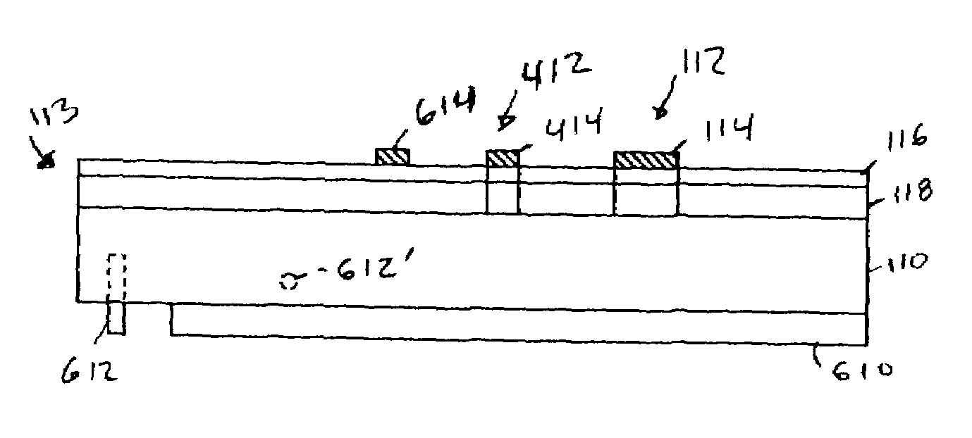
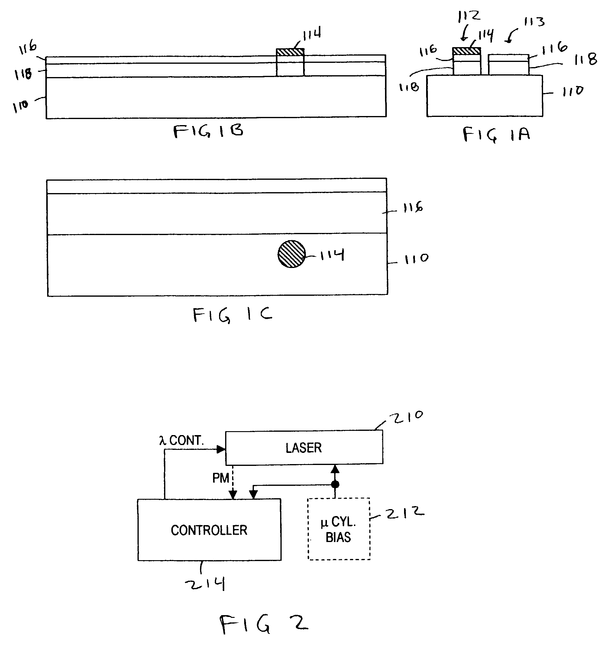
[0031]One exemplary embodiment of the present invention, illustrated in FIGS. 1A, 1B and 1C, is monitored waveguide device 100 including a waveguide 113 and a micro-cylinder 112. FIG. 1A is a side plan drawing, FIG. 1B is a front plan drawing and FIG. 1C is a top plan drawing of the of device 100. The exemplary device includes a substrate 110, wave guide layer 118 and cladding layer 116. Waveguide material 118 desirably exhibits low optical loss and a relatively high index of refraction in the desired wavelength band. Although, in the devices described below, the waveguide material 118 may be various III / V materials, such as InP, GaAs, AlGaAs, or InGaAsP, other possible materials choices are contemplated. Possible alternatives for the waveguide material 118 include: doped silica (similar to optical fibers); silicon; germanium; and dielectric materials such as SiO2 and SiN, which have low optical loss characteristics for the desired wavelength band.

[0032]Cladding layer 116 and substr...


PUM


Abstract

An optical device includes an optical waveguide through which light propagates and a micro-resonator structure including an optical sensor. The micro-resonator is configured to resonate at a wavelength of light that may be transmitted through the optical waveguide. When light at that wavelength is transmitted through the optical waveguide, it resonates in the resonator and is detected by the optical sensor to produce an electrical signal. The optical resonator may be a micro-cylinder, disc or ring resonator and may be coupled to the waveguide via evanescent coupling or leaky-mode coupling. Multiple resonators may be implemented proximate to the waveguide to allow multiple wavelengths to be detected. When the waveguide is coupled to a tunable laser, signals provided by the optical sensor may be used to tune the wavelength of the laser.

Description

[0001]The present invention claims benefit of priority from U.S. provisional application No. 60 / 375,881 filed Apr. 26, 2002 the contents of which are incorporated herein by reference.BACKGROUND OF THE INVENTION[0002]The present invention relates to optical monitoring devices and in particular to a micro-resonator which is coupled to an optical device to produce an electronic signal when the wavelength of the light provided in the optical device is within the resonance bandwidth of the micro-resonator.[0003]Optical monitors are used with many optical devices. They may be used, for example, to determine the wavelength and / or optical power of light produced by a semiconductor laser in order to tune the laser. Optical monitors may also be used to determine the losses in an optical system, such as a electro-absorptive modulator or semiconductor optical amplifier, by measuring both the input energy and output energy of the system either over a broad band of wavelengths or in a specific na...

Claims


Application Information

Patent Timeline
Patent Type & Authority Patents(United States)
IPC IPC(8): G02B6/12H01S5/026H01S5/0687
CPCH01S5/0687H01S5/026G01J3/0205G01J3/12G01J3/0216G01J3/0259
Inventor ANDERSEN, JOHN KAIFRATESCHI, NEWTON C.
Owner BROADCOM INT PTE LTD
Why Eureka
Try Eureka