

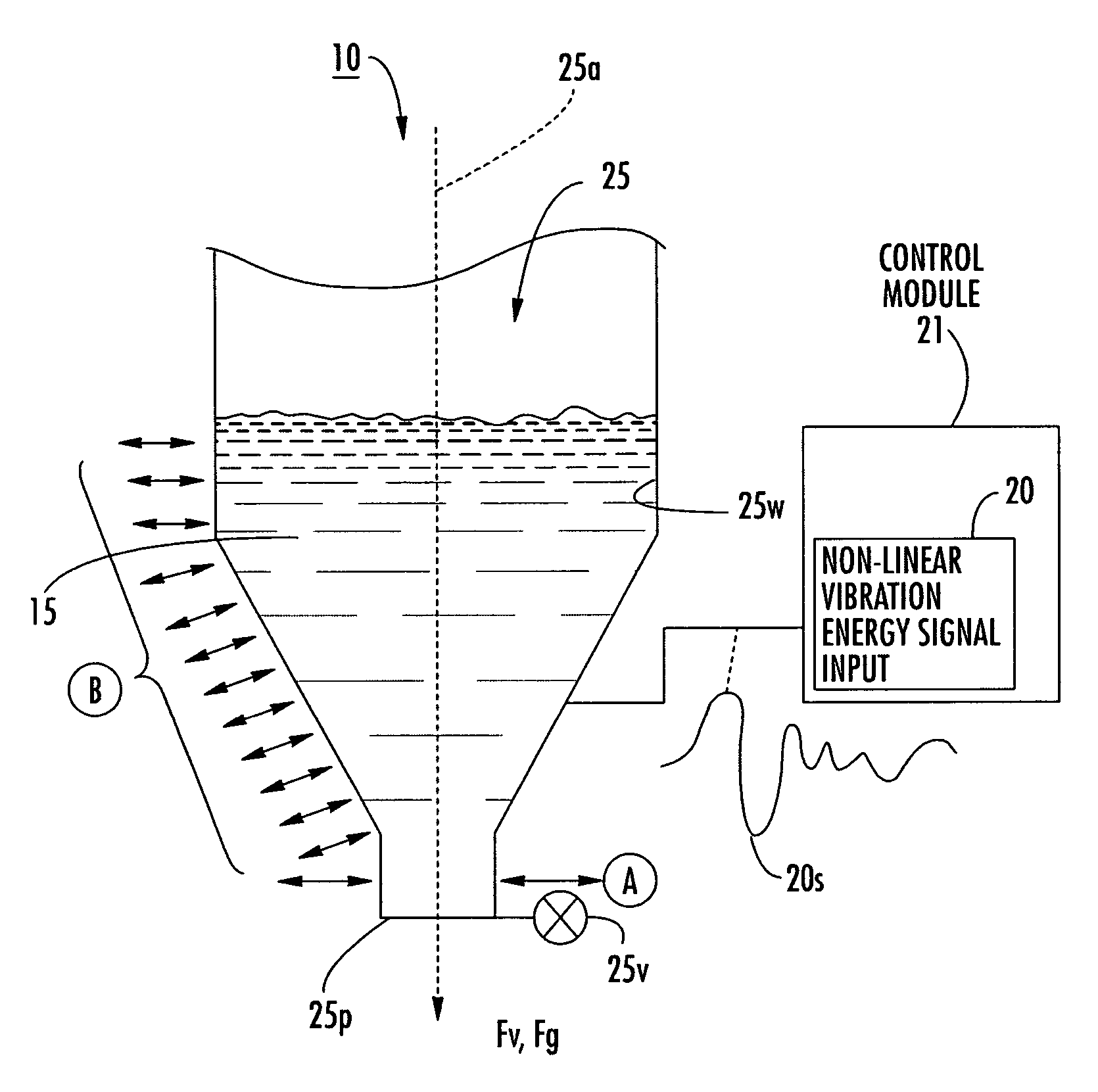
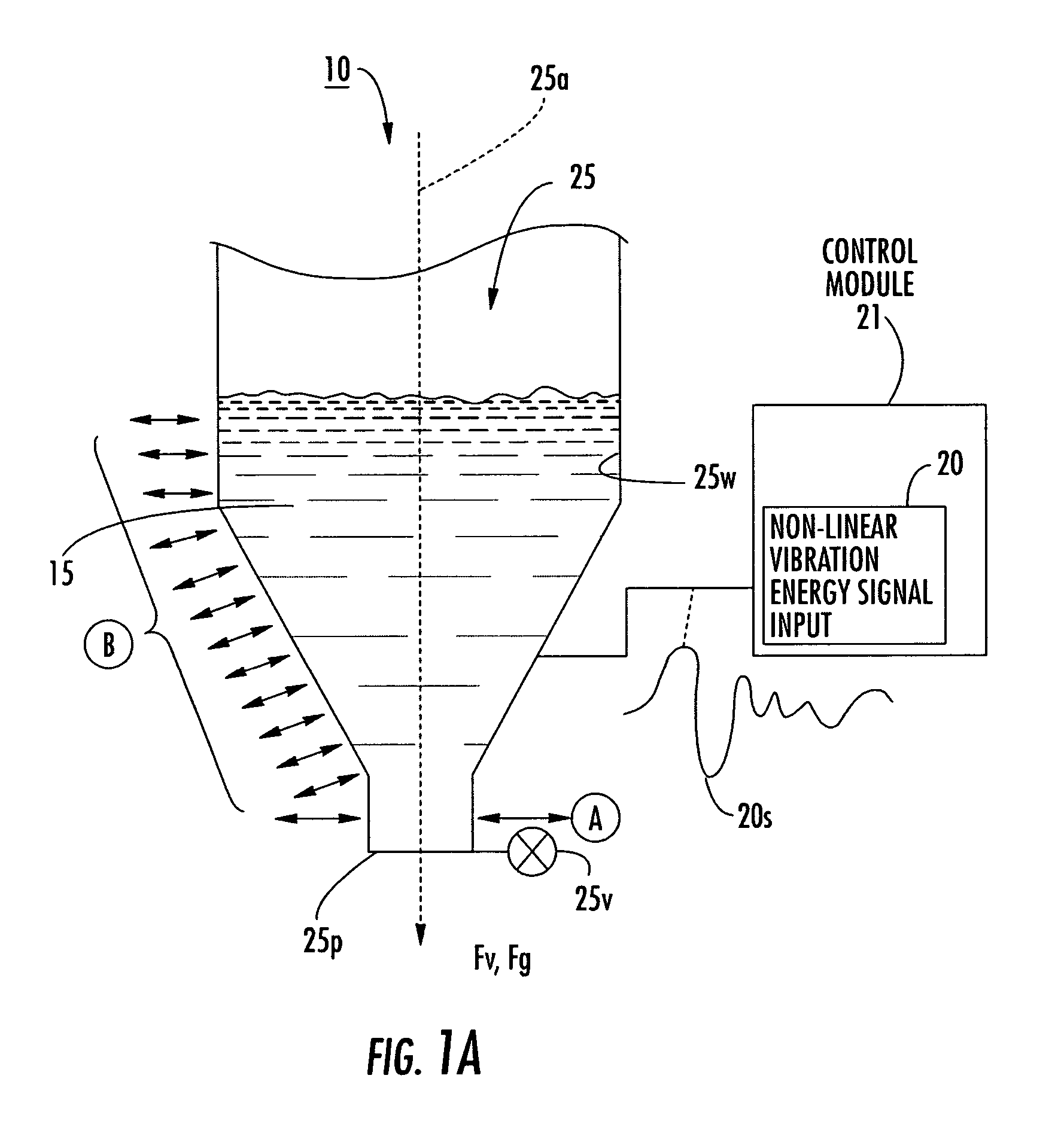
Dry powder dose filling systems and related methods
a filling system and dry powder technology, applied in the field of dry powder substance dispensing, can solve the problems of difficult precise filling, limited filling dose range, and poor flow properties of dry powders
- Summary
- Abstract
- Description
- Claims
- Application Information
AI Technical Summary
Benefits of technology
Problems solved by technology
Method used
Image

Examples
example 1
[0158]The data in Tables 2 and 3 were obtained using the apparatus illustrated in FIG. 13. The signal generator was a 200V amplifier. The carrier frequency selected for the Inhalac 230 dry powder (a dry powder from Meggle Gmbh, Wasserburg, Germany, that has a 230 mesh size when sieved by the manufacturer) was 7500 Hz. The signal (identified as arb 2 signal) used to vibrate the piezoelectric polymer layer may be selected and / or expressed using one or more of Equations 1–6 herein. The exemplary excitation signal includes the superposition of four modulating frequencies ranging from 10–15 Hz.
[0159]
Mass Flow Rate Data for Inhalac 230ConditionsMass in reservoir (mg) 350Channel Angle (deg.) 24Carrier Freq. (Hz)7500Signalarb2PowderInhalac 230primed (s) ~60mass flowdelta t (s)mass (mg)rate (mg / s)39.573.19039.773.25739.743.247310.863.620310.463.487AVG3.360ST DEV0.184RSD5.5%
PUM
| Property | Measurement | Unit |
|---|---|---|
| frequencies | aaaaa | aaaaa |
| carrier frequencies | aaaaa | aaaaa |
| carrier frequency | aaaaa | aaaaa |
Abstract
Description
Claims
Application Information