Centrifugal separator with scraper or piston for discharging solids

a centrifugal separator and solids technology, applied in centrifuges, filtration separation, separation processes, etc., can solve the problems of reduced solids recovery yield, unstable operation, and ineffective removal of wet or sticky solids by radial-motion scrapers, and achieve stable operation, high critical speed, and high speed

Inactive Publication Date: 2006-01-17
CARR ROBERT BRET
View PDF34 Cites 20 Cited by
  • Summary
  • Abstract
  • Description
  • Claims
  • Application Information

AI Technical Summary

Benefits of technology

[0008]In one aspect, the disclosed centrifugal separator provides for automatic discharge of solids by means of either an axial-motion scraper or a piston / extrusion assembly with exchangeable parts, having variable speed operation for greater versatility. The axial-motion scraper is used with hard-packed or friable solids, and includes an integral feed liquid accelerator and feed holes. The scraper blades flex outwardly under high centrifugal force to lock the scraper in place against the bowl. This provides a rigid or fixed end condition for the lower end of the scraper shaft to allow for high critical speed of the shaft. The scraper provides less surface area for solids to stick to, and can be used in conjunction with relatively long separator bowls.
[0009]The piston / extrusion assembly is used for pasty, sticky solids that can be extruded. A centrate valve at the top of the bowl is used to enable the centrate (separated liquid) to be discharged during a feed mode of operation, and then to close off the top of the bowl for a solids discharge mode of operation. The assembly further includes a piston that sits at the bottom of the bowl during the feed mode of operation. The piston has an integral feed accelerator and feed holes through which the feed liquid passes. These holes also provide exit paths for the solids during the extrusion that takes place in the solids discharge mode of operation. The piston / extrusion assembly can be used with sticky solids that other existing centrifuges cannot discharge efficiently, and provides for nearly complete removal of the solids, which is desirable for example when the solids contain valuable materials.
[0010]In another aspect, the disclosed centrifugal separator includes a separator bowl suspension that employs a short, stiff spindle and a spherically mounted bearing housing. Conceptually, the arrangement is analogous to a vertical rotating beam with a simply supported upper end. This arrangement has a very high critical speed as compared to existing centrifuges. It is possible to achieve a critical speed greater than the highest operating speed, so that the critical speed is not encountered during operation. The spherically mounted bearing housing restrains axial motion of the separator bowl and provides for stable operation at higher speeds than prior mounting arrangements. In one embodiment, the bearing housing comprises a semi-spherical portion having an upper semi-hemispherical portion and a lower semi-hemispherical portion, and a cylindrical portion.

Problems solved by technology

However, such a radial-motion scraper does not effectively remove wet or sticky solids which may have a consistency like that of peanut butter.
As a result, the solids recovery yield is reduced and the remaining solids undesirably contaminate the separator.
An additional consideration is potential for axial movement of the separator bowl, for example in the presence of imbalance or the motion of liquid axial waves in the bowl, which can result in unstable operation.

Method used


Image

  • Centrifugal separator with scraper or piston for discharging solids
  • Centrifugal separator with scraper or piston for discharging solids
  • Centrifugal separator with scraper or piston for discharging solids

Examples


Embodiment Construction

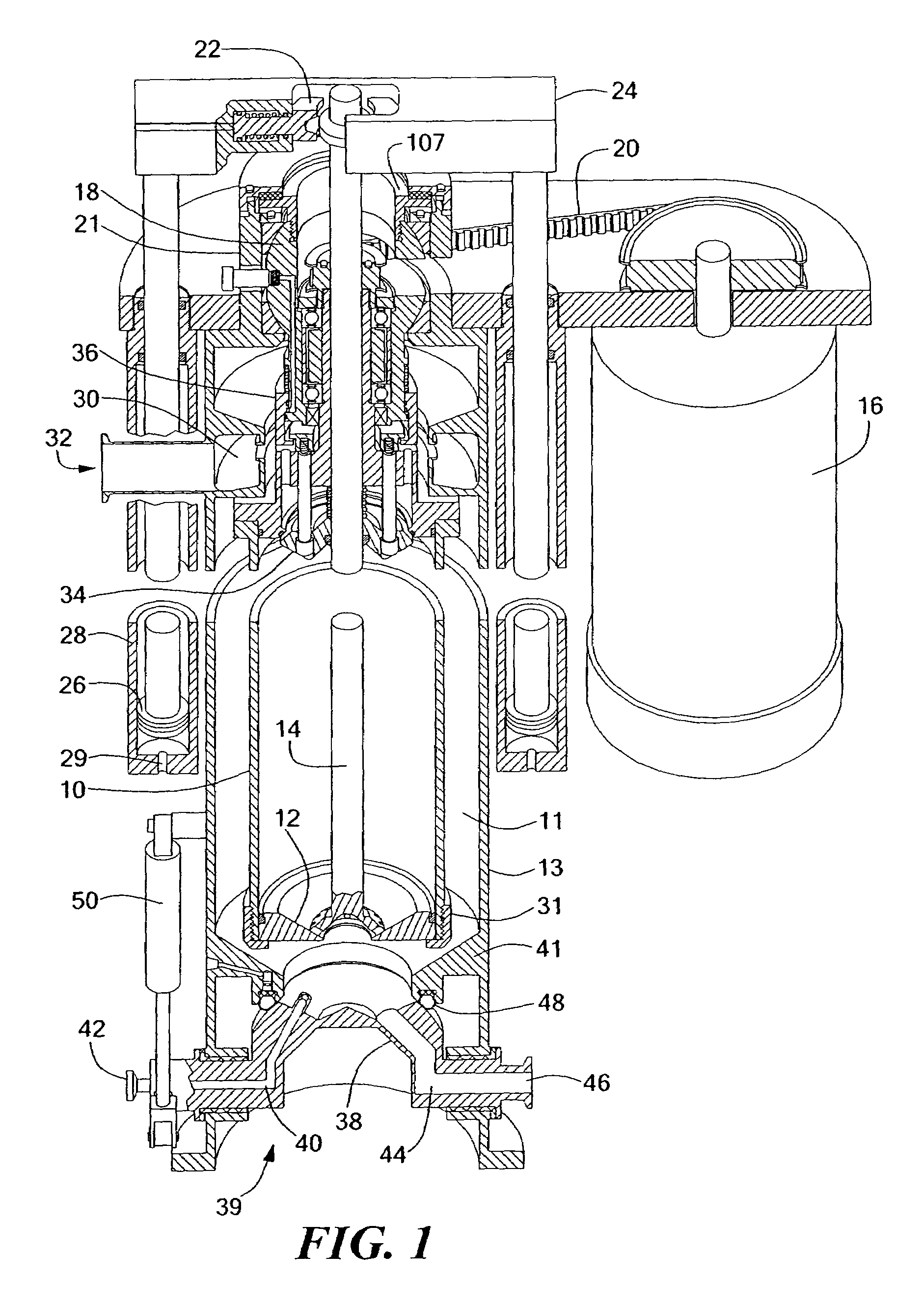
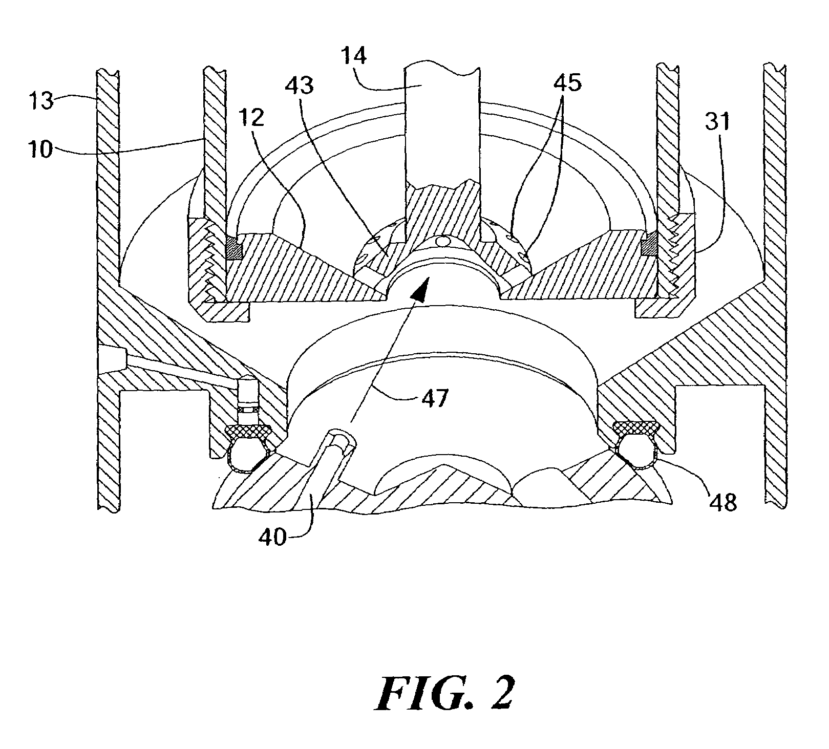
[0031]FIG. 1 shows a centrifugal separator in vertical section, with a middle portion removed so as to illustrate a horizontal section as well. The centrifugal separator includes a cylindrical separator bowl 10 mounted in a central region 11 of a separator housing 13. The separator bowl 10 is preferably a tubular type bowl having a relatively small diameter D and a length L such that the ratio of L / D is approximately 5 / 1 or greater. Mounted within the separator bowl 10 is a piston assembly consisting of a piston head 12 connected to a piston shaft 14.

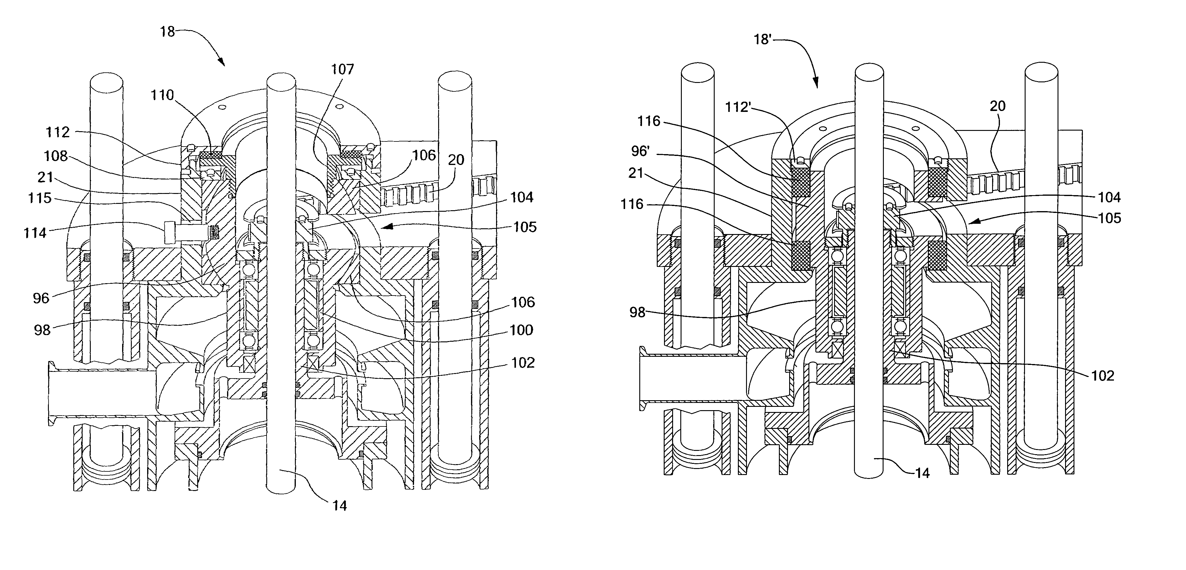
[0032]A variable speed drive motor 16 is connected to a drive pulley of a spherically mounted bearing and spindle assembly 18. The connection is made by a drive belt 20 at a collar-like extension 21 of the upper end of the separator housing 13. The drive motor 16 is controllably operated to rotate the separator bowl 10 at desired speeds for separating the feed liquid. A piston shaft clutch 22 is mounted in a crosshead 24 of a piston act...


PUM

PropertyMeasurementUnit
specific gravityaaaaaaaaaa
speedsaaaaaaaaaa
gravityaaaaaaaaaa

Abstract

A centrifugal separator provides for the discharge of solids by either an axial-motion scraper or a piston / extrusion assembly. The axial-motion scraper is used with hard-packed or friable solids, and includes an integral feed liquid accelerator and feed holes. The piston / extrusion assembly is used with pasty solids, and includes a piston extending into a separator bowl and having openings permitting fluid communication across the piston. After high-speed separation is complete, a centrate valve closes one end of the bowl, and the piston is moved axially in the bowl by an actuator. Accumulated solids are scraped from the sides of the bowl and extruded out of the piston openings for discharge from the bowl. A bowl suspension employs a spherical mounting structure and a short, stiff spindle. A spherical portion of a bearing housing is mounted in a spherical mounting region at one end of the separator, with a cylindrical portion of the bearing housing extending along the rotational axis. A bearing and the spindle of the separator bowl are mounted within the cylindrical portion of the bearing housing. The suspension is retained by a stiff resilient ring and retaining member secured to the separator in compressive contact with the spherical portion of the bearing housing.

Description

CROSS REFERENCE TO RELATED APPLICATIONS[0001]This application is a continuation of U.S. application Ser. No. 10 / 412,943, now U.S. Pat. No. 6,776,752 filed on Apr. 14, 2003 entitled, AUTOMATIC TUBE BOWL CENTRIFUGE FOR CENTRIFUGAL SEPARATION OF LIQUIDS AND SOLIDS WITH SOLIDS DISCHARGE USING A SCRAPER, and also claims priority under 35 U.S.C. § 119(e) of U.S. Provisional Patent Application No. 60 / 372,153 filed Apr. 12, 2002, the whole of which are hereby incorporated by reference herein.STATEMENT REGARDING FEDERALLY SPONSORED RESEARCH OR DEVELOPMENT[0002]Not Applicable.BACKGROUND OF THE INVENTION[0003]The present invention generally relates to centrifuges and in particular to a centrifuge enabling automatic discharge of solids that accumulate during separation.[0004]Many different types of centrifugal separators are known for separating heterogeneous mixtures into components based on specific gravity. A heterogeneous mixture, which may also be referred to as feed material or feed liqui...

Claims


Application Information

Patent Timeline
Patent Type & Authority Patents(United States)
IPC IPC(8): B04B9/12B04B11/08B04B1/02B04B11/05B04B11/06
CPCB04B1/02B04B9/12B04B11/05B04B11/08B04B11/06B04B2009/085B04B2005/0485
Inventor CARR, ROBERT B.
Owner CARR ROBERT BRET
Why Eureka
Try Eureka