
High power rotary transformer with bus duct assembly

Active Publication Date: 2006-01-17
GENERAL ELECTRIC CANADA INC A CO OF CANADA
View PDF21 Cites 2 Cited by
  • Summary
  • Abstract
  • Description
  • Claims
  • Application Information

AI Technical Summary

Benefits of technology

[0006]The present invention relates to a bus duct assembly for use in a rotary transformer that does not significantly weaken the shaft structure adjacent the drive motor of the rotary transformer thereby eliminating or reducing the requirement for the use of exotic steels of relatively increased wall thickness.
[0009]It is also within the realm of the present invention to provide a bus duct assembly that is formed from two L shaped sections whose leads are each respectively mounted through a corresponding set of exit holes in a corresponding shaft portion with the longer leg of the L of each section extending axially parallel to the shaft axis and being interconnected. By having interconnecting bus duct, it is simpler to remove the upper shaft section during field servicing because the bus duct assembly unplugs. Further, the use of two bus duct sections within the shaft coupled together simplifies assembly of each bus duct section within its corresponding shaft section. Another advantage with the bus duct assembly is that the flexible connections between the bus duct and the windings of the rotary transformer rotor do not need to be disconnected prior to removal of the upper shaft. Instead the electrical connection between the bus duct and the rotor winding is automatically accomplished by the disconnection of the bus duct sections. The flexible connections and all the connections underneath the rotor on the rotary transformer between the bus duct and the rotor can remain connected when the upper shaft is removed. This is a significant time saving feature for field servicing.

Problems solved by technology

This leaves insufficient material in the shaft wall where the exit holes are cut to safely transmit the torque from the drive motor to the rotor of the rotary transformer.
These holes create enormous stress concentrations in the shaft where the torquing movement of the drive motor is applied that must be compensated with very expensive and exotic steels.

Method used


Image

  • High power rotary transformer with bus duct assembly
  • High power rotary transformer with bus duct assembly
  • High power rotary transformer with bus duct assembly

Examples


Embodiment Construction

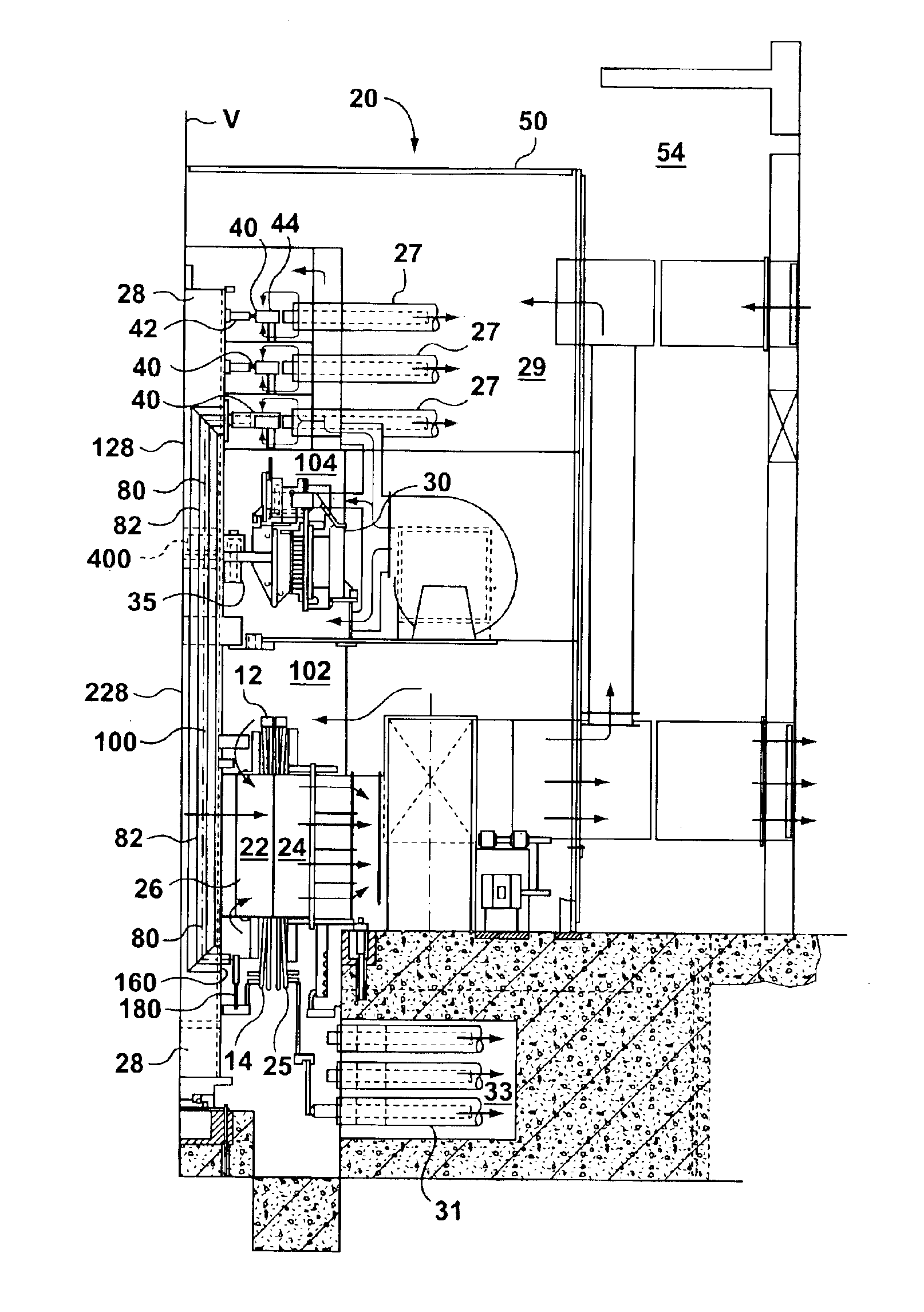
[0020]Referring to FIG. 1 there is shown a rotary transformer 20 which includes both the rotor assembly 22 and a stator 24. The rotor assembly 22 includes a rotor core section 26, first and second rotor end windings 12, 14, slip rings or collector rings 40, and a rotatable shaft 28. Rotor assembly 22 is rotatable about a vertical axis V of its rotatable shaft 28 in both a clockwise direction and the counter-clockwise direction. Rotation of rotor assembly 22 is effected by a drive motor 30. It should be understood that while the preferred embodiment shows a vertically orientated rotary transformer, the orientation of the rotary transformer may be along another axis such as, for example, a horizontal axis.

[0021]The rotary transformer 20 is a high voltage, high current environment of alternating voltage and current. Rotary transformer system 20 is connected to transfer electrical power between first electrical system (example first electrical grid) and a second electrical system (for e...


PUM


Abstract

A rotary transformer has a bus duct assembly that extends through the hollow shaft of a rotary transformer from collector or slip rings positioned above a drive motor for the rotary transformer to end windings of the rotor positioned most remote from the drive motor. By positioning the leads of the bus duct connection with the rotor end windings on the rotor end windings most remote form the drive motor, the shaft strength and integrity is not reduced due to the torque applied by the drive motor. Further, the shaft is formed from two coupled shaft sections and the bus duct assembly comprises two L shaped sections each positioned substantially within a corresponding shaft section. The bus duct sections are interconnected to complete the bus duct assembly making it simpler to remove the first or upper shaft section from the second or lower shaft section during field servicing. Further, the use of the two bus duct sections within the shaft coupled together simplifies assembly of each bus duct section within its corresponding shaft section.

Description

FIELD OF THE INVENTION[0001]The present invention relates to a high power rotary transformer having a bus duct assembly mounted within the rotating shaft of the transformer.BACKGROUND OF THE INVENTION[0002]A high power rotary transformer may be utilized to transform electrical power from one power grid operating at one frequency to a second power grid operating at a second frequency. U.S. Pat. No. 5,953,225 issued Sep. 14, 1999 to Larsen discloses a rotary transformer that includes a power recovery system to recover and apply to the transferee grid a power differential attributable to mechanical power channeled to a rotatable shaft of the rotary transformer.[0003]Another such rotary transformer assembly is disclosed in Canadian patent application serial number 2,351,895 published Dec. 30, 2001 to Martin and Rehder. This rotary transformer assembly utilizes three phases of isolated bus duct passing through the center of the rotating shaft to connect the rotor of the rotary transforme...

Claims


Application Information

Patent Timeline
IPC IPC(8): H01R39/08H02K13/02H02K47/26
CPCH02K47/26H02K13/02
Inventor WHITE, MICHAEL WALTERMILLS, BRUCE WILLIAMREHDER, ROBERT HENRY
Owner GENERAL ELECTRIC CANADA INC A CO OF CANADA
Features
  • Generate Ideas
  • Intellectual Property
  • Life Sciences
  • Materials
  • Tech Scout
  • Unparalleled Data Quality
  • Higher Quality Content
  • 60% Fewer Hallucinations
Learn More