Optical record medium, optical information processing apparatus, and optical recording/reproducing method

Inactive Publication Date: 2006-01-17
PANASONIC CORP
View PDF19 Cites 10 Cited by
  • Summary
  • Abstract
  • Description
  • Claims
  • Application Information

AI Technical Summary

Benefits of technology

[0017]In the above-mentioned optical recording/reproducing apparatus, information can be recorded/rep

Problems solved by technology

As a result, heat is generated locally in the recording

Method used


Image

  • Optical record medium, optical information processing apparatus, and optical recording/reproducing method
  • Optical record medium, optical information processing apparatus, and optical recording/reproducing method
  • Optical record medium, optical information processing apparatus, and optical recording/reproducing method

Examples


Example

Embodiment 1

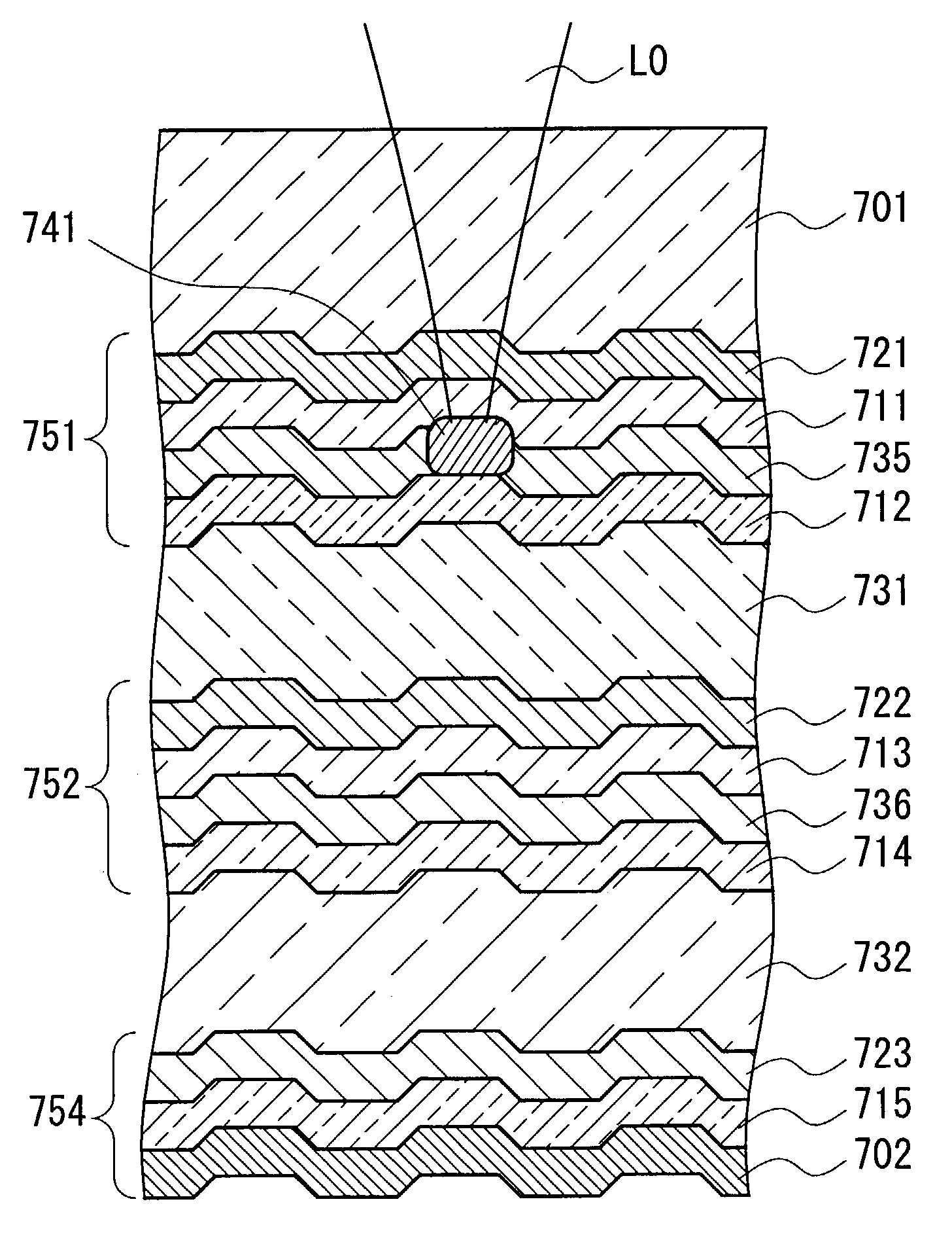
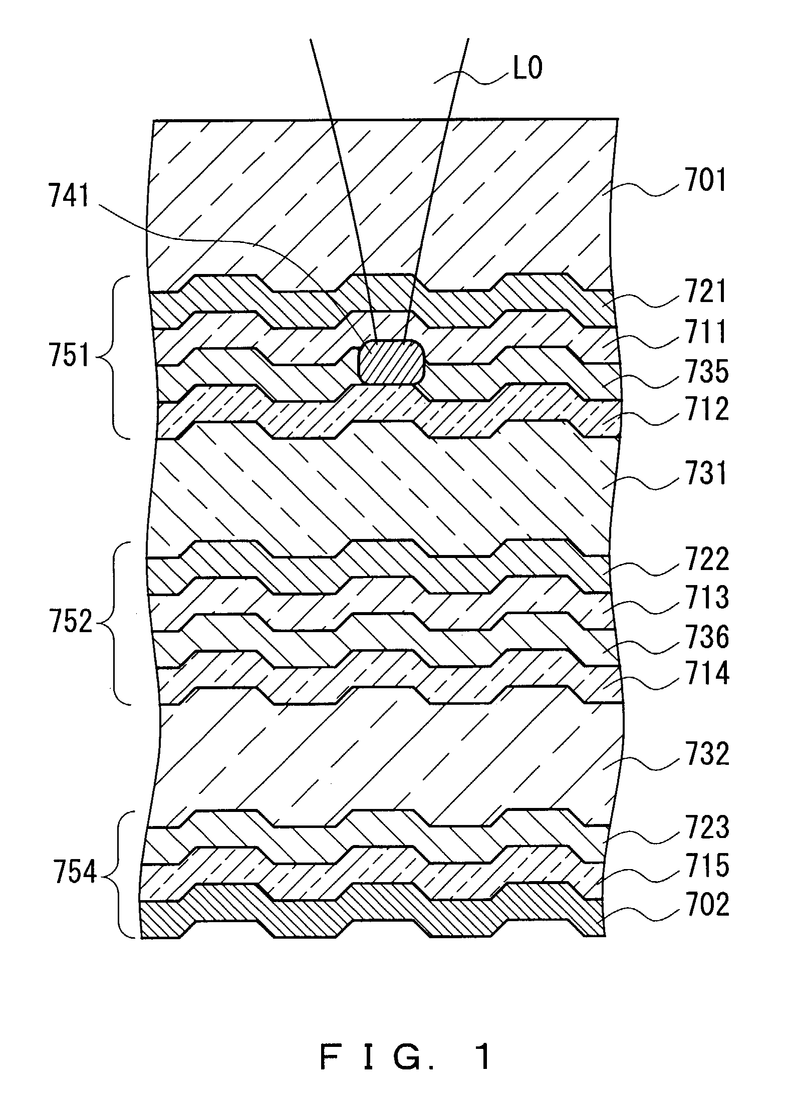
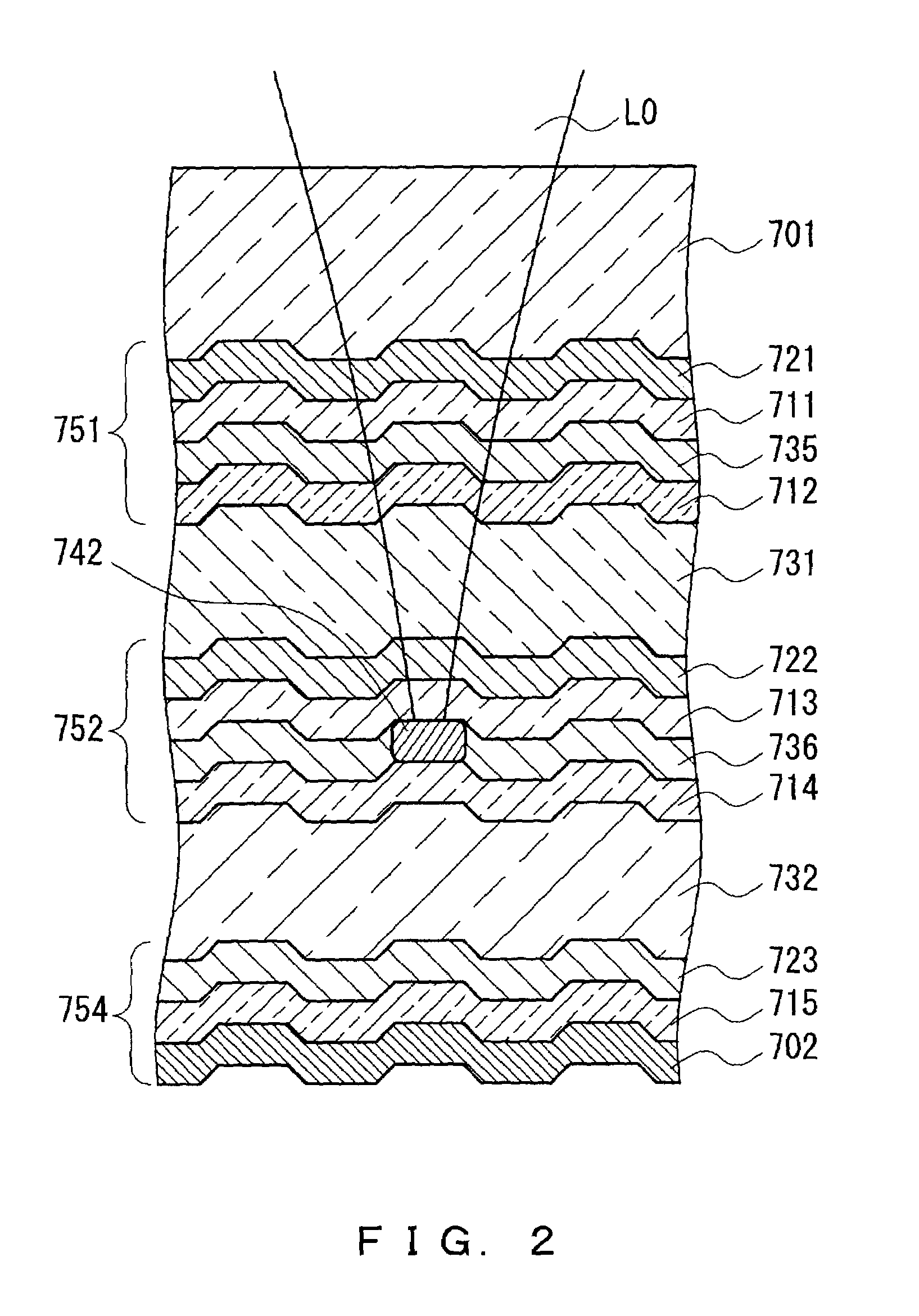
[0030]FIG. 1 is a cross-sectional view showing a configuration of an optical recording medium of Embodiment 1. This optical recording medium is a multilayer recording medium in which a first recording layer 751, a second recording layer 752 and a final recording layer 754 are formed in this order from a light (L0) incident side. Separation films 731 and 732 are provided between the respective recording layers.

[0031]The first recording layer 751 and the second recording layer 752 have the same layer configuration. In the layer configuration, a recording film 721 (722), a dielectric film 711 (713) and a reflection control film (variable reflective film) 735 (736), and a dielectric film 712 (714) are provided in this order from the light (L0) incident side.

[0032]Further, the final recording layer 754 is provided so that the separation film 732 is interposed between the final recording layer 754 and the second recording layer 752. The final recording layer 754 is composed of...

Example

Embodiment 2

[0043]An optical recording medium of Embodiment 2 is obtained by applying a configuration shown in FIG. 6 to the recording layers 751 and 752 other than the final recording layer 754 of the optical recording medium of Embodiment 1. FIG. 6 shows that information is recorded / reproduced with respect to the first recording layer 751.

[0044]In FIG. 6, reference numerals 711 and 712 denote dielectric films, and 735 denotes a reflection control film. These films are the same as those in Embodiment 1. A recording film 721 is substantially transparent to light L0, and records information based on the difference in a refractive index. A heat absorption and generation film 746 is made of a material semi-transparent to the light L0. For example, in the case where the light L0 is laser light with a wavelength of about 650 mm, a thin film of amorphous Si can be used as the heat absorption and generation film 746. The light L0 is absorbed by the heat absorption and generation film 746 t...

Example

Embodiment 3

[0049]An optical recording medium of Embodiment 3 is obtained by applying a configuration shown in FIG. 7 to the recording layers 751 and 752 other than the final recording layer 754 of the optical recording medium of Embodiment 1. FIG. 7 shows that information is recorded / reproduced with respect to the first recording layer 751.

[0050]In FIG. 7, reference numerals 711 and 712 denote dielectric films. Reference numeral 735 denotes a reflection control film. These films are the same as those in Embodiment 1. A recording film 721 is substantially transparent to light L1 with a wavelength λ1 and light L2 with a wavelength λ2, and records information by utilizing the variation in refractive index with heat. A wavelength-selection and absorption film 743 is made of a material that is semi-transparent to the light L2, and is transparent to the light L1. For example, when the wavelength λ1 of the light L1 is about 430 nm and the wavelength λ2 of the light L2 is about 650 nm, the...


PUM


Abstract

A first recording layer and a second recording layer among a plurality of recording layers have a recording film and a reflection control film composed of silver oxide, and the reflection control film is interposed between dielectric films. The reflection control film utilizes heat generated from the recording film by light irradiation, thereby forming a high-reflection region in a portion at a temperature equal to or higher than a threshold temperature for forming a high-reflection region. Thus, an optical loss in the portions other than a recording layer to be recorded/reproduced is reduced, whereby a light efficiency is enhanced.

Description

TECHNICAL FIELD[0001]The present invention relates to an optical recording medium for recording / reproducing information optically, such as an optical disk and an optical card, and an optical information processing apparatus and an optical recording / reproducing method for recording / reproducing information with respect to the optical recording medium.BACKGROUND ART[0002]Recently, along with the increasing computerization of the society, there is an increasing demand for external storage apparatuses with a large capacity. In optical recording of information, due to the diffraction limit determined by the wavelength of light and the numerical aperture of an objective lens, an increase in density by reducing the size of a recording pit conventionally is limited. In order to solve this problem, a multilayer optical recording medium having a plurality of recording layers has been proposed. As the recording layer used for a multilayer optical recording medium, a semi-transparent film capabl...

Claims


Application Information

Patent Timeline
IPC IPC(8): G11B7/24G11B7/00G11B7/004G11B7/0045G11B7/125G11B7/1275G11B7/1356G11B7/257G11B7/258
CPCB82Y10/00G11B7/004G11B7/00454G11B7/00455G11B7/1275G11B7/1356G11B7/259G11B7/24038G11B2007/25716G11B7/252G11B2007/0013G11B2007/25706G11B2007/2571G11B2007/25715
Inventor YAMAMOTO, HIROAKIKADOWAKI, SHIN-ICHI
Owner PANASONIC CORP
Why Eureka
Try Eureka