LED brightness control system for a wide-range of luminance control

a technology of luminance control and led light control, which is applied in the direction of electroluminescent light sources, semiconductor lamps, lasers, etc., can solve the problem of low duty cycle and achieve the effect of low duty cycl

Active Publication Date: 2006-01-17
ROCKWELL COLLINS INC
View PDF15 Cites 470 Cited by
  • Summary
  • Abstract
  • Description
  • Claims
  • Application Information

AI Technical Summary

Benefits of technology

[0012]Lower brightness can be achieved by Pulse-Width-Modulating (PWM) the voltage to the LED with a higher peak LED current level than a low level DC current. But PWM over such a large range (20,000 to 1) is also difficult, resulting in very low duty cycles. By combining linear control of the LED current over a limited range with PWM over a limit

Problems solved by technology

But PWM over such a large range (20,000 to 1) is

Method used


Image

  • LED brightness control system for a wide-range of luminance control
  • LED brightness control system for a wide-range of luminance control
  • LED brightness control system for a wide-range of luminance control

Examples


Embodiment Construction

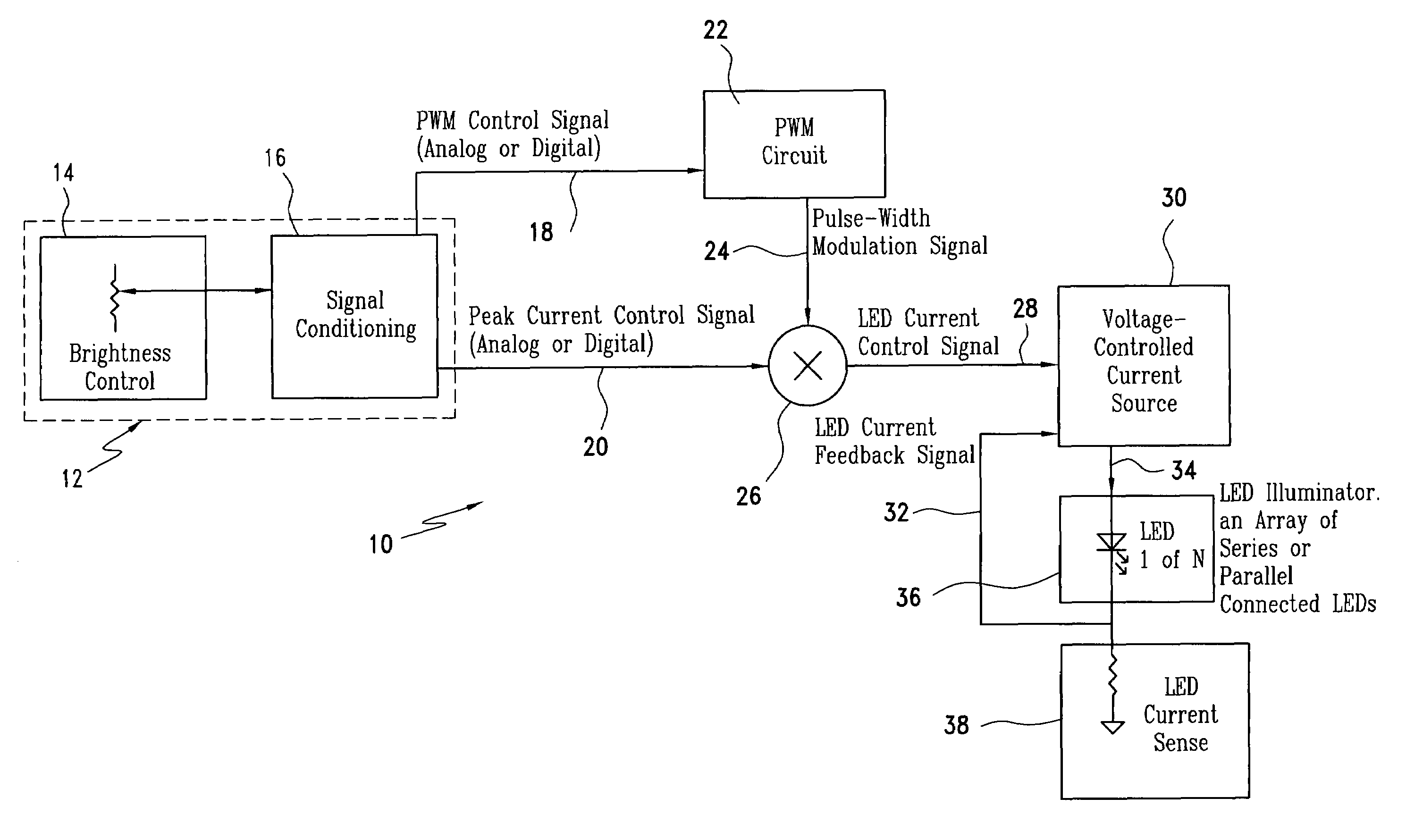
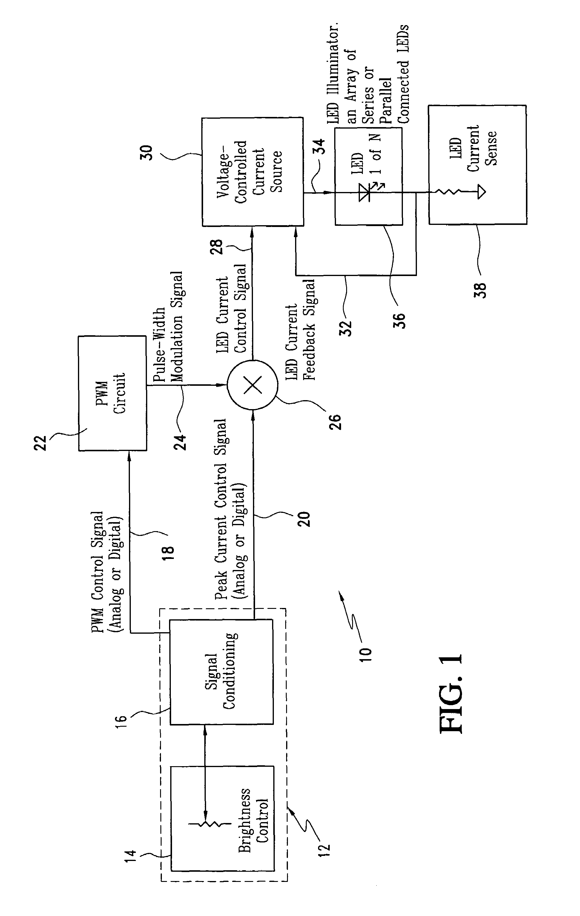
[0022]Referring now to the drawings and the characters of reference marked thereon, FIG. 1 illustrates a preferred embodiment of the LED brightness control system of the present invention, designated generally as 10, showing the system in a fundamental form. The LED brightness control system 10 includes a brightness control module, designated generally as 12. The brightness control module typically includes a brightness control element 14 connected to a signal conditioning element 16. The brightness control element 14 may comprise, for example, a variable resistive element with a voltage output signal. The signal conditioning element 16 typically comprises buffering amplifiers with offset, scaling, and possibly non-linear control, or an embedded display control computer system having a digital look-up table. The brightness control module 12 provides a pulse width modulation (PWM) control signal 18 and a peak current control signal 20.

[0023]A pulse width modulation (PWM) converter ci...


PUM


Abstract

The LED brightness control system for a wide range of luminance control includes a brightness control module that provides a pulse width modulation (PWM) control signal and a peak current control signal. A pulse width modulation (PWM) converter circuit receives the PWM control signal and converts it to a PWM signal. A multiplier receives the PWM signal and the peak current control signal from the brightness control module and multiplies the same to provide a light emitting diode (LED) current control signal with a variable “on” time as well as variable “on” level. A voltage-controlled current source utilizes the LED current control signal and an LED current feedback signal for providing an LED current. An LED illuminator array receives the LED current. A current sensing element connected to the LED illuminator array for providing an LED current feedback signal representing LED peak current. The voltage-controlled current source controls a drive voltage to the LED illuminator array at a commanded level.

Description

BACKGROUND OF THE INVENTION[0001]1. Field of the Invention[0002]The present invention relates to LED brightness control systems and more particularly to the control of an LED source for LCD backlighting over a wide range.[0003]2. Description of the Related Art[0004]In the manufacture and use of liquid crystal displays, backlighting from a light source is dispersed evenly beneath the surface of a liquid crystal display to allow optimal viewing of the display in all types of ambient light conditions. Depending upon the light conditions of the environment, the light intensity of the backlight may be adjusted to allow optimal viewing of the liquid crystal display. Liquid crystal display backlights frequently employ fluorescent lamps. However, fluorescent lamps require high power and a high voltage source. Another method of providing backlight is through the utilization of light emitting diodes. Light emitting diodes are utilized for backlights in liquid crystal displays due to their dim...

Claims


Application Information

Patent Timeline
IPC IPC(8): H01S3/13
CPCH05B33/0818H05B33/0848Y02B20/347H05B45/14H05B45/325Y02B20/30
Inventor MICK, PERRY J.
Owner ROCKWELL COLLINS INC
Why Eureka
Try Eureka