
Packaging system

a packaging system and packaging technology, applied in the field of packaging system and method, can solve the problems of article spinning off the conveyor, difficult to apply any force to adjust the orientation of the article, and the handling of lightweight articles, etc., to achieve the effect of reducing placement distances, high efficiency, and high pickup rates

Inactive Publication Date: 2006-01-24
ISHIDA CO LTD
View PDF16 Cites 6 Cited by
  • Summary
  • Abstract
  • Description
  • Claims
  • Application Information

AI Technical Summary

Benefits of technology

[0022]The bomb door opening geometry allows the bomb doors to open to discharge the pack cleanly, preferably so that the pack does not touch the bomb doors as the pack drops. In other words, the pack is effectively left in free space when the bomb doors open. This provides a very repeatable drop, which, in turn, provides accurate collations that are formed for presentation to a pickup head of the pickup device.
[0023]The bomb door assembly can also be used to re-space bags fed from a source that may be intermittent or from a source that supplies a flow of packs on a variable mark space ratio. The bomb doors can be programmed to smooth out these variances so that a constant stream of packs is presented downstream of the bomb doors. This assists the pick-and-place robot assembly in working at very high efficiency without the need for high-tech camera systems. Also, picking and placing of packs are optimized, allowing for higher pickup rates, because of reduced placement distances and the pickup head readily finding the collation or pack.

Problems solved by technology

There are particular problems about the handling of lightweight articles.
For example, a lightweight article, such as a packet of potato chips, may travel at a speed along a conveyor such that it is very difficult to apply any force to adjust the article's orientation.
Even a slight force applied to an article may send the article spinning off the conveyor.

Method used


Image

  • Packaging system
  • Packaging system
  • Packaging system

Examples


Embodiment Construction

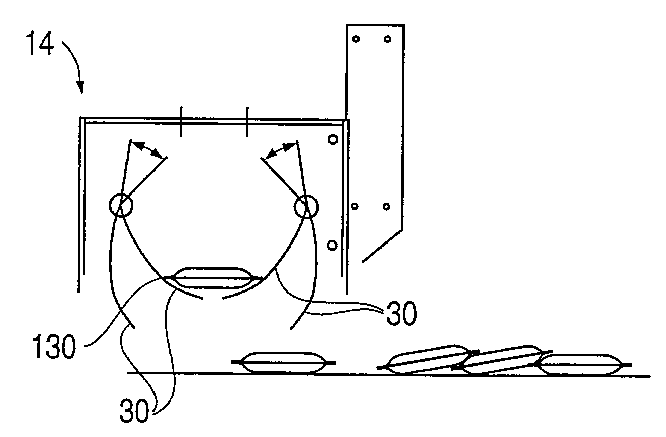
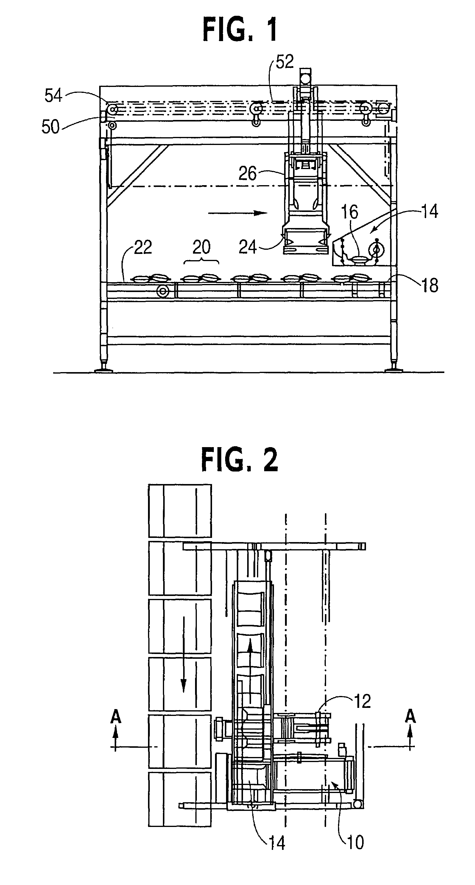
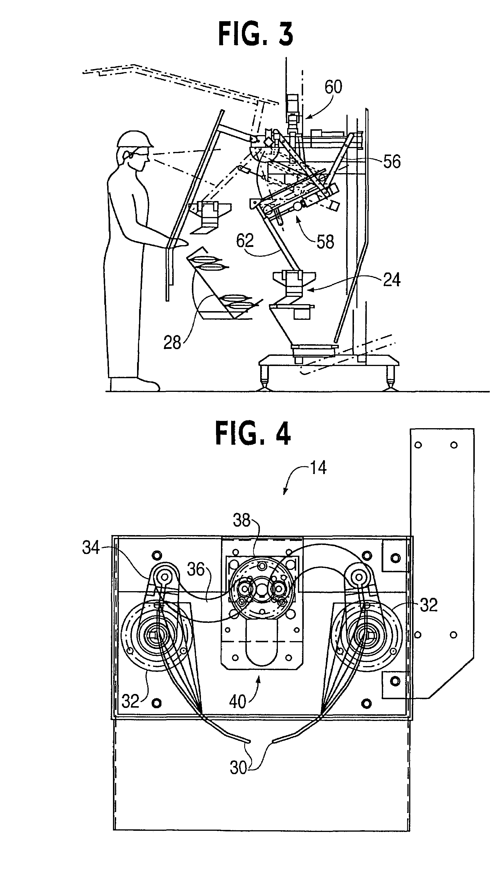
[0039]The invention is described by way of an example. The accompanying drawings show an apparatus used for packaging articles, such as packets of snack foods (e.g., potato chips). The articles 16 are delivered to a packaging apparatus via an infeed conveyor 10 (see FIGS. 2 and 9). A sensor of a photocell device 12 detects the arrival of an article 16. An individual article 16 is delivered to a bomb door assembly 14. From the bomb door assembly 14, an article 16 is dropped a short distance onto a first conveyor belt 18, which is generally short in length. These devices run intermittently, under the control of a microprocessor, which receives signals from the photocell device 12 and also controls the operation of the bomb door assembly 14. The intermittent operation of the first conveyor 18 is controlled so that successive articles 16 are assembled into desired arrays. In FIG. 1, these arrays are shown, for example, as shingled pairs 20. The arrays are conveyed on a main conveyor bel...


PUM

PropertyMeasurementUnit
displacementaaaaaaaaaa
speedaaaaaaaaaa
forceaaaaaaaaaa

Abstract

A packing system for articles. According to one embodiment of the invention, a receiving and dropping assembly comprising one or more doors that are displaceable between a holding configuration and a dropping configuration. The doors define a receptacle while in the holding configuration. The receptacle receives and holds an article, which is received by a leading edge of the article being guided by guide surfaces in the doors. The doors drop the article being held while in the dropping configuration. An output conveyor line receives the articles dropped by the receiving and dropping assembly. A controller controls the dropping and conveyance of the articles to convey the dropped articles along the output conveyor line in predetermined arrays. A pick-and-place robot system picks up the articles or arrays of articles from the output conveyor line and places the picked up articles in receptacles.

Description

CROSS-REFERENCE TO RELATED APPLICATION[0001]This application is based on, and claims priority to, UK Patent Application No. 0117504.1filed on Jul. 18, 2001, the contents of which are hereby incorporated by reference.BACKGROUND OF THE INVENTION[0002]1. Field of the Invention[0003]The present invention relates to a packaging system and method. In particular, the present invention relates to a packaging system and method for packaging articles in receptacles such as trays and boxes. More particularly, the present invention relates to a packaging system and method for packaging lightweight articles such as bags of potato chips and other snack foods.[0004]2. Description of the Related Art[0005]Conventionally, bags of potato chips and the like are produced with a high degree of automation. It is then often desired to place bags in shallow trays, suitable for display at a point of sale. Single trays may be intended to receive a controlled mixture of different products (e.g., different pota...

Claims


Application Information

Patent Timeline
Patent Type & Authority Patents(United States)
IPC IPC(8): B65B35/30B25J19/00B25J9/00B65B5/10B65B35/12B65B35/32B65B35/36B65B35/44B65G47/52
CPCB65B5/101B65G47/52B65B35/12
Inventor BENNETT, ROBERT
Owner ISHIDA CO LTD
Learn More