Administration of CPAP treatment pressure in presence of apnea

a technology of positive airway pressure and treatment pressure, which is applied in the direction of application, diagnostic recording/measuring, operating means/releasing devices of valves, etc., can solve the problems of decreased ventilation, decreased blood oxygenation, and disruption of sleep, so as to increase the treatment pressure, reduce the existing cpap, and increase lung volume

Inactive Publication Date: 2006-01-24
RESMED LTD
View PDF48 Cites 180 Cited by
  • Summary
  • Abstract
  • Description
  • Claims
  • Application Information

AI Technical Summary

Benefits of technology

[0037]The present invention can be combined with an independent pressure increase in response to indicators of partial upper airway obstruction such as snoring or changes in shape of the inspiratory flow-time curve. In this way it is possible in most subjects to achieve pre-emptive control of the upper airway, with pressure increases in response to partial upper airway obstruction preventing the occurrence of closed airway apneas. In the minority of subjects in whom pre-emptive control is not achieved, this combination will also correctly increase the CPAP pressure in response to those closed airway apneas that occur at low CPAP pressure without prior snoring or changes in the shape of the inspiratory flow-time curve. Furthermore, the combination will avoid falsely increasing the CPAP pressure in response to open airway apneas induced by high pressure.

Problems solved by technology

Apneas lead to decreased blood oxygenation and thus to disruption of sleep.
This also leads to decreased ventilation (hypopnea), decreased blood oxygenation and disturbed sleep.
However, it is not desirable to increase CPAP pressure in response to open airway apneas, firstly because this leads to an unnecessarily high pressure, and secondly because the high pressure can reflexly cause yet further open airway apneas, leading to a vicious circle of pressure increase.
This ‘forced oscillation method’ requires the ability to modulate the mask pressure at 4 Hz, which increases the cost of the device.
Furthermore, the method does not work in the presence of high leak, and can falsely report that the airway is closed if the subject has a high nasal or intrapulmonary resistance.

Method used


Image

  • Administration of CPAP treatment pressure in presence of apnea
  • Administration of CPAP treatment pressure in presence of apnea
  • Administration of CPAP treatment pressure in presence of apnea

Examples


first embodiment

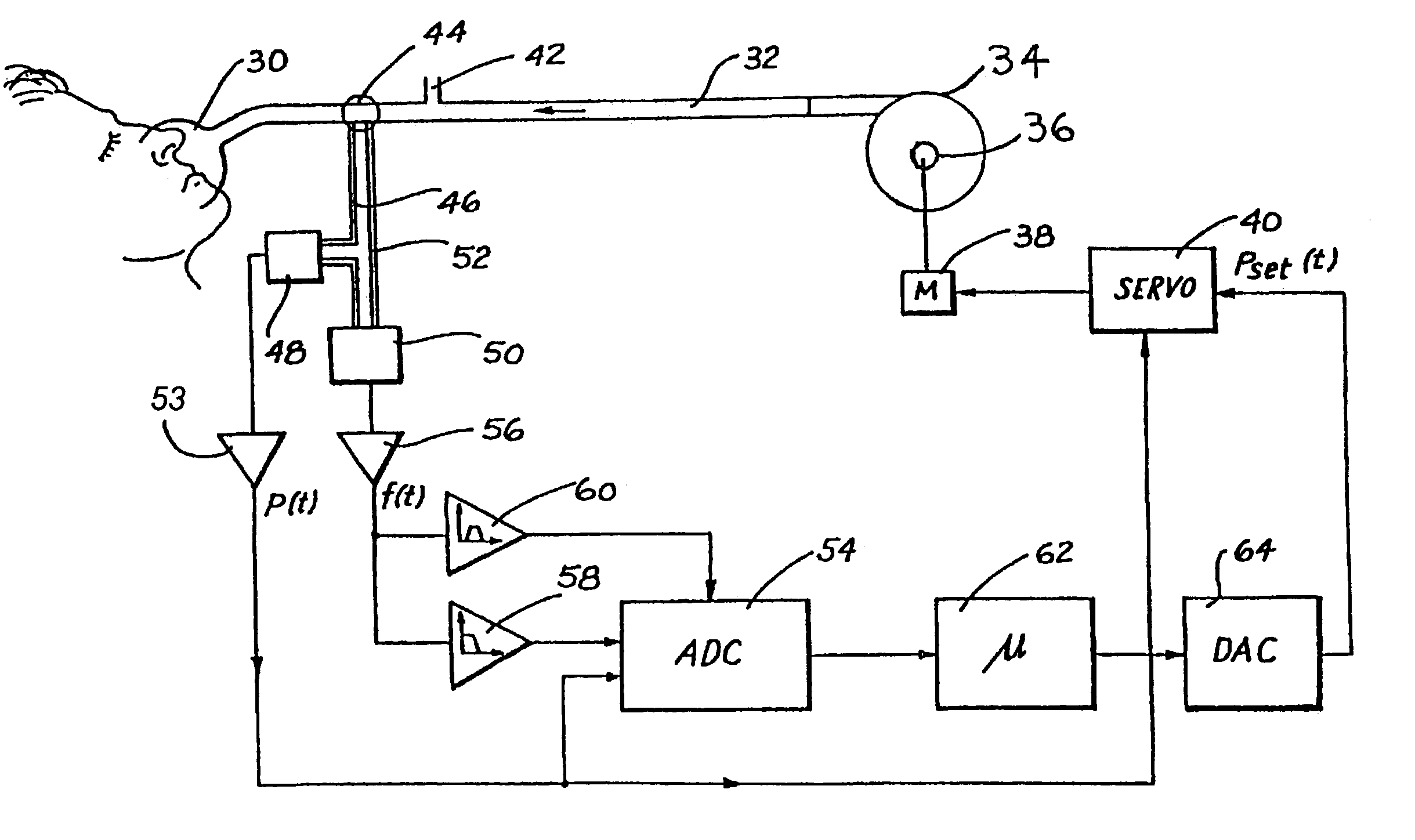
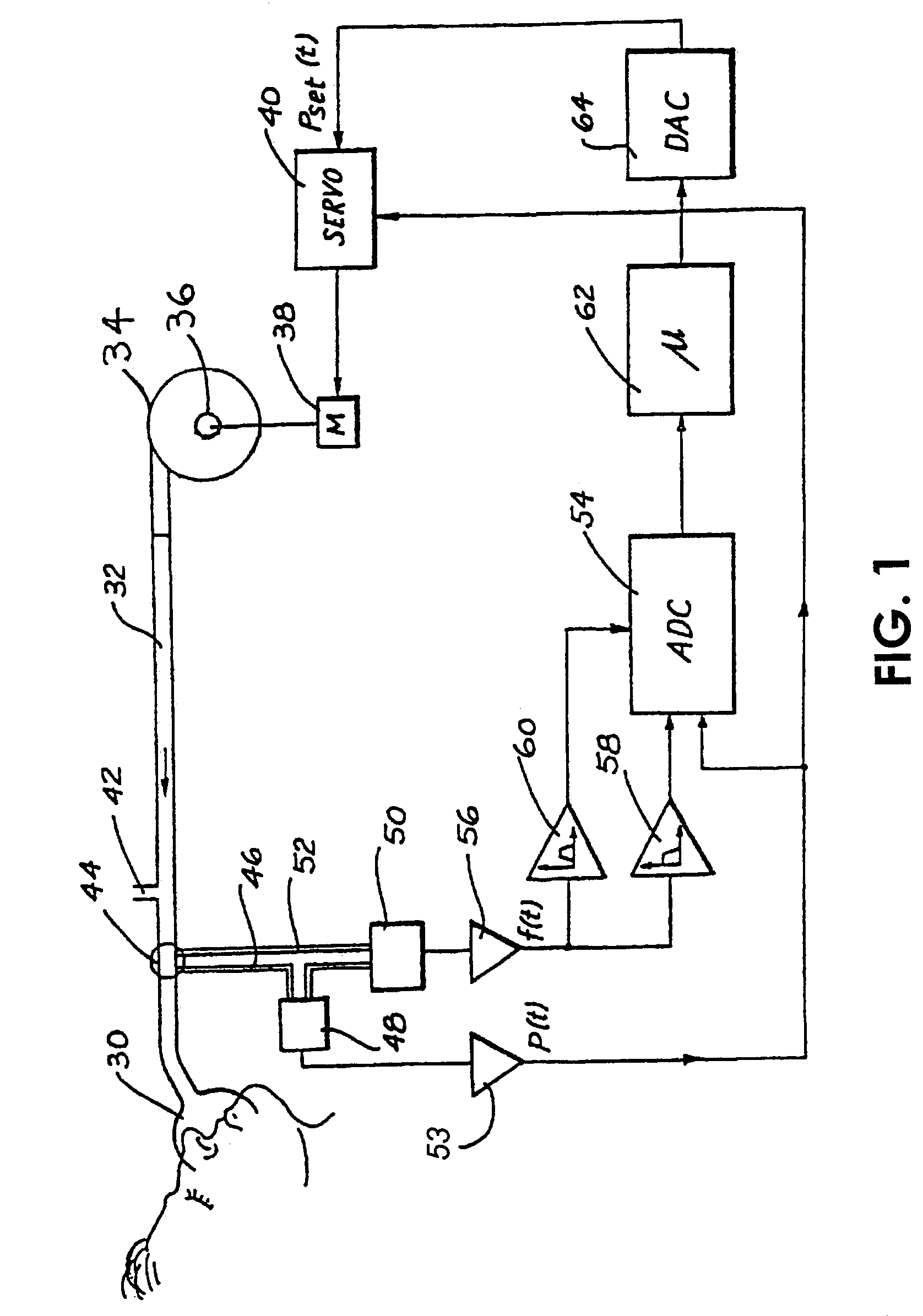
[0056]The methodology put into place by the controller 62 will now be described. In a first embodiment, there is a pressure response to apneas, but not to indicators of partial obstruction, and therefore snore detection bandpass filter 60 is not required.

[0057]An initial CPAP treatment pressure, typically 4 cmH2O, is supplied to the subject. The FLOW signal is processed to detect the occurrence of an apnea (as will presently be discussed) and, at the same time, the Pmask signal is recorded. When it is determined that an apnea has occured its duration is recorded. At the same time Pmask is compared against a pressure threshold, Pu. If Pmask is at or above Pu the controller will act to maintain or reduce that pressure. If, on the other hand, Pmask is below Pu, the controller will act to increase the treatment pressure by an amount ΔP.

[0058]In a preferred form, ΔP is determined as follows:

ΔP=[Pu−P]f(ta)   (1)

where

[0059]ΔP is the change in pressure (cmH2O)

[0060]Pu is the pressure thresh...

second embodiment

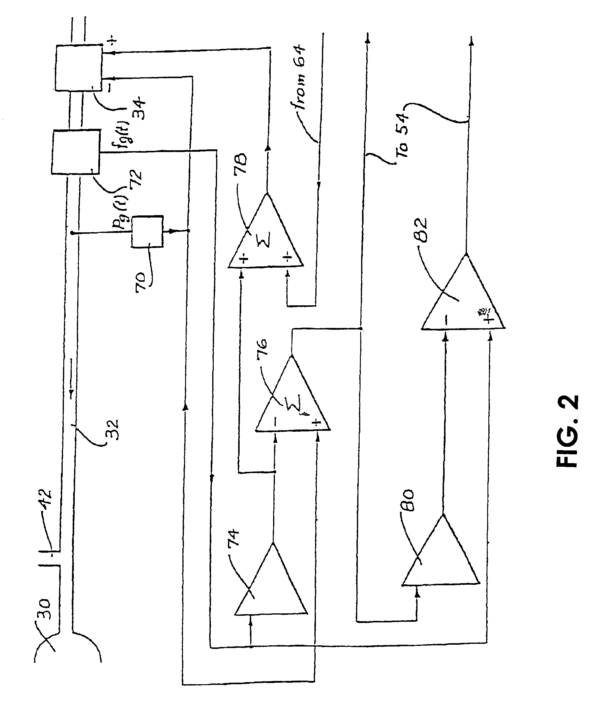
[0077]This second embodiment is implemented using the following pseudocode.

[0078]

Set initial CPAP pressure to 4 cmH2O.Set apnea duration to zero Clear “start of breath” flag REPEAT every 1 / 50 of a second   Sample mask pressure (in cmH2O), mask airflow (in L / sec), andsnore (1 unit corresponds loosely to a typical snore).   Calculate mask leak as mask airflow low pass filtered with a timeconstant of 10 seconds.   Adjust snore signal for machine noise.   Check for presence and duration of any apnea.   Check for start of breath.   IF start of breath flag set:     IF apnea duration greater than 10 seconds AND current  CPAP pressure less than 10 cmH2O:      Set delta pressure for this apnea to (10 − current    CPAP pressure) / 6 times 8 cmH2O per minute of apnea    duration.      Add delta pressure for this apnea to total delta    pressure due to apnea, and truncate to 16 cmH2O      Reset apnea duration to zero.     ELSE      Reduce total delta pressure due to apnea with a time    constant ...

third embodiment

[0096]As previously discussed, one prior art method for avoiding unnecessary increases in pressure in response to open airway apneas is to determine the conductance of the airway during an apnea using the forced oscillation method, and only increase mask pressure if the conductance is less than a threshold. However, if the nasal airway is narrow or if the subject has lung disease, the airway conductance may be low even in the presence of an open airway and the forced oscillation method may still falsely increase pressure in response to open airway apneas. Conversely, the combination of the forced oscillation method with embodiments of the present invention has the added advantage that in most cases open airway apneas are correctly detected by the ‘forced oscillation method’, but in those cases where the forced oscillation method falsely reports a closed airway, the mask pressure will not increase above 10 cmH2O, thus preventing run-away increases in pressure. This is demonstrated in...


PUM


Abstract

CPAP treatment apparatus is disclosed having a controllable flow generator (34, 38, 40) operable to produce breathable gas at a treatment pressure elevated above atmosphere to a patient by a delivery tube (32) coupled to a mask (30) having connection with a patient's airway. A sensor (44, 50, 56, 58) generates a signal representative of patient respiratory flow, that is provided to a controller (54, 62, 64). The controller (54, 62, 64) is operable to determine the occurrence of an apnea from a reduction in respiratory airflow below a threshold, and if an apnea has occurred, to determine the duration of the apnea and to cause the flow generator (34, 38) to increase the treatment pressure. In one preferred form the increase in pressure is zero if the treatment pressure before the apnea exceeds a pressure threshold. Below the pressure threshold the increase in pressure is an increasing function of the duration of the apnea multiplied by the difference between the pressure threshold and the current treatment pressure.

Description

[0001]This application is a continuation of application Ser. No. 10 / 281,743, filed Oct. 28, 2002. now U.S. Pat. No. 6,817,361, issued Nov. 16, 2004, which is a continuation of application Ser. No. 09 / 531,915, filed Mar. 21, 2000, now U.S. Pat. No. 6,502,572, issued Jan.7, 2003, which is a continuation-in part of application Ser. No. 09 / 008,743, filed Jan. 19, 1998, now U.S. Pat. No. 6,367,474, issued Apr. 9, 2002, entitled “Administration of CPAP Treatment Pressure in Presence of Apnea”.FIELD OF THE INVENTION[0002]This invention relates to the administration of continuous positive airway pressure (CPAP) treatment for partial or complete upper airway obstruction.BACKGROUND OF THE INVENTION[0003]In the Sleep Apnea syndrome a person stops breathing during sleep. Cessation of airflow for more than 10 seconds is called an “apnea”. Apneas lead to decreased blood oxygenation and thus to disruption of sleep. Apneas are traditionally (but confusingly) categorized as either central, where the...

Claims


Application Information

Patent Timeline
Patent Type & Authority Patents(United States)
IPC IPC(8): A61M16/00
CPCA61M16/00A61M16/06A61M16/0051A61M16/0069A61B5/4818A61B5/0205A61M16/0003A61M16/0875A61B5/4836A61M2016/0036A61M16/024
Inventor BERTHON-JONES, MICHAELFARRUGIA, STEVEN PAUL
Owner RESMED LTD
Why Eureka
Try Eureka