Fuel injection valve

a technology of fuel injection valve and fuel injection valve, which is applied in the direction of fuel injection apparatus, charge feed system, engine components, etc., can solve the problems of high temperature acting on the seal, temperature-dependent sealing effect of the metallic seal, and inability to ensure the full-throttle strength of nonmetallic seal materials

Inactive Publication Date: 2006-01-24
ROBERT BOSCH GMBH
View PDF18 Cites 28 Cited by
  • Summary
  • Abstract
  • Description
  • Claims
  • Application Information

AI Technical Summary

Benefits of technology

[0010]The fuel injector according to the present invention may provide the advantage that only a change in the geometry of the nozzle body results in sealing. Because the sealing ridges are configured in one piece with the nozzle body, the seal is required to have a sealing function only with regard to the contiguous component. Another consequence is that no materials that may be damaged as a result of the temperatures that occur are used in the immediate vicinity of the combustion chamber. The purely metallic seal is a constituent of a component that is used in any case, so that furthermore no additional corrosion protection (for example, due to possible contact corrosion) is necessary.

Problems solved by technology

A disadvantage of the sealing approach described in German Published Patent Application No. 198 49 210 is the high temperature acting on the seal.
With direct-injection internal combustion engines, full-throttle strength of nonmetallic seal materials may not be ensured.
The approach described in German Published Patent Application No. 198 08 068 has the disadvantage that the sealing effect of the metallic seal is temperature-dependent.
The complex materials that are used in the manufacture of metallic seals which deform in temperature-dependent fashion are also disadvantageous.
The result is to increase not only development costs for the alloy but also costs for utilization in series production.
Installation of the bimetallic element e.g. in a groove is difficult, however, since the properties of the metals change if one of the two metals experiences an inelastic deformation during installation

Method used


Image

  • Fuel injection valve
  • Fuel injection valve
  • Fuel injection valve

Examples


Embodiment Construction

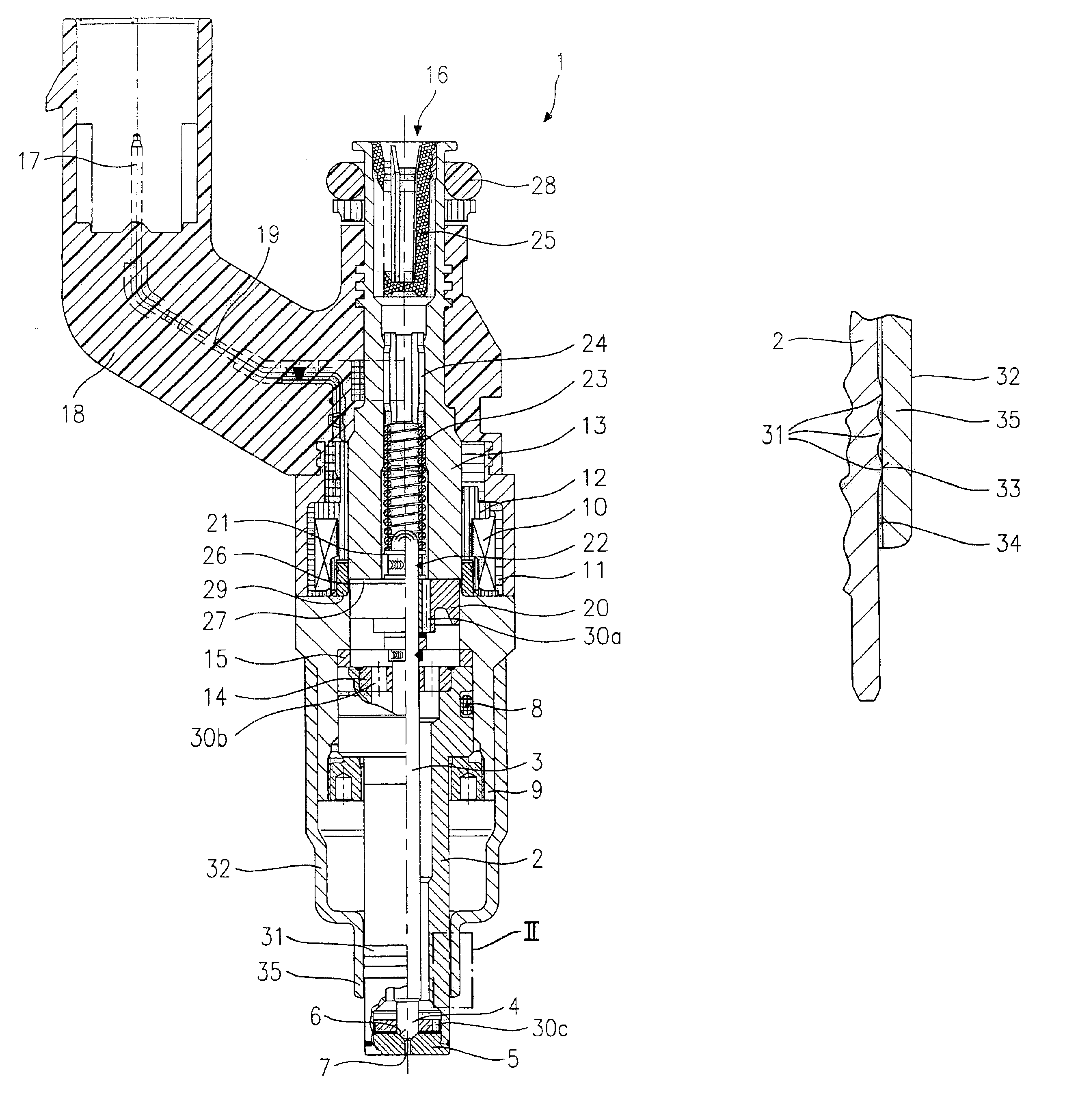
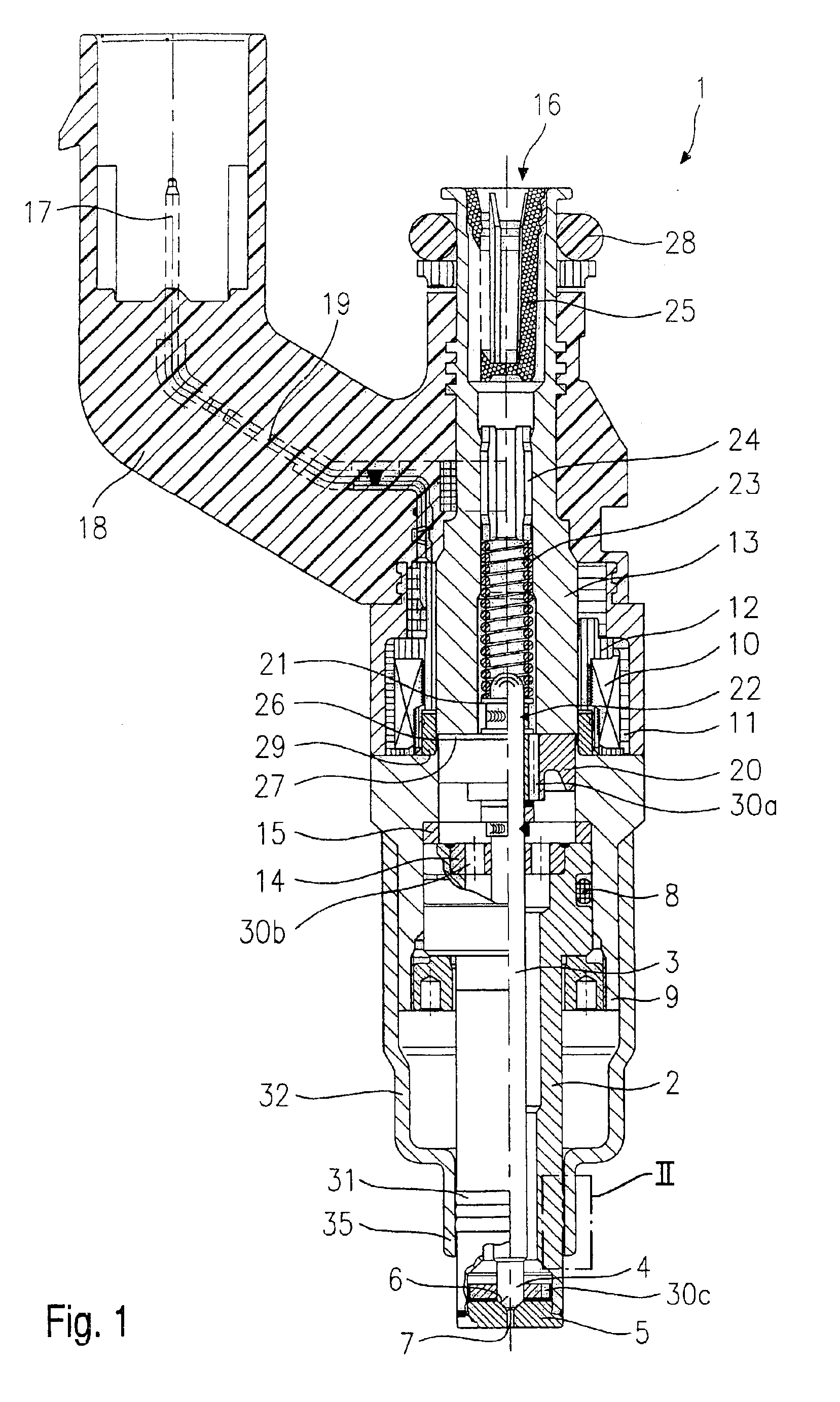
[0018]For better comprehension of the present invention, an example embodiment of a fuel injector 1 according to the present invention will first be explained briefly with reference to FIG. 1 in an overall presentation in terms of its constituents.

[0019]Fuel injector 1 is embodied in the form of a fuel injector 1 for fuel injection systems of mixture-compressing, sparkignited internal combustion engines. Fuel injector 1 is suitable for direct injection of fuel into a combustion chamber (not depicted) of an internal combustion engine.

[0020]Fuel injector 1 includes a nozzle body 2 in which a valve needle 3 is positioned. Valve needle 3 is in working engagement with a valve closure element valve-closure member which coacts with a valve-seat surface 6, positioned on a valve seat element 5, to form a sealing seat. In the example embodiment, fuel injector 1 is an electromagnetically actuated fuel injector 1 that possesses at least one spray discharge opening 7. Nozzle body 2 is sealed by ...


PUM


Abstract

A fuel injector for fuel injection systems of internal combustion engines includes a nozzle body. At a downstream end of the nozzle body at least one spray discharge opening is arranged. A sealing element is arranged on the nozzle body for sealing with respect to a contiguous component. At least one circumferential sealing ridge that forms a press fit with a contiguous component is arranged on the nozzle body as the sealing element.

Description

FIELD OF THE INVENTION[0001]The present invention relates to a fuel injector.BACKGROUND INFORMATION[0002]A fuel injector that includes a nozzle body which is tubular on its downstream side, and at whose downstream end a sealing seat and a spray discharge opening are positioned, is described in German Published Patent Application No. 198 49 210. The tubular portion of the nozzle body is insertable into a receiving bore of a cylinder head. The nozzle body is sealed with respect to the receiving bore of the cylinder head, which has a diameter corresponding to the radial extension of the nozzle body, with a seal that has approximately the geometry of a hollow cylinder.[0003]For positional retention of the seal on the nozzle body, the nozzle body includes a circumferential groove which is made, for example, by turning down the nozzle body and into which the seal is inserted. Elastic materials that may be slid over the nozzle body for installation in the groove may be used as materials.[0...

Claims


Application Information

Patent Timeline
Patent Type & Authority Patents(United States)
IPC IPC(8): B05B1/30F02M51/06F02M51/08F02M61/16
CPCF02M51/0671F02M61/168F02M2200/8061F02M2200/16
Inventor REITER, FERDINAND
Owner ROBERT BOSCH GMBH
Why Eureka
Try Eureka