
Self-propelled imaging system

Inactive Publication Date: 2006-01-24
G I VIEW LTD (IL)
View PDF7 Cites 39 Cited by
  • Summary
  • Abstract
  • Description
  • Claims
  • Application Information

AI Technical Summary

Benefits of technology

[0004]The present invention seeks to provide an improved imaging system which is self-propelled, suitable for imaging body lumens, such as the gastrointestinal (GI) tract. The imaging system of the invention may be sterile and disposable, and may be manufactured at very low cost. The system causes virtually no pain to the patient, being of very low friction and providing maximum comfort and flexibility. The system provides excellent visibility and full movement control.

Problems solved by technology

In this manual technique, patients may often complain of abdominal pain and distention because the colon is extended or excessively dilated, thereby necessitating stopping the endoscopic procedure.
Furthermore, it is not unusual for the colon to bleed and be accidentally perforated.
Insertion of an endoscope through the sigmoid colon and into the descending colon, or through the splenic flexure, the transverse colon, the hepatic flexure or parts affected by previous operations may also be accompanied with difficulty.
Because of these reasons, a colonoscopy is typically performed by a relatively few number of skilled practitioners, and the rate of patient pain and discomfort is high.

Method used


Image

  • Self-propelled imaging system
  • Self-propelled imaging system
  • Self-propelled imaging system

Examples


Embodiment Construction

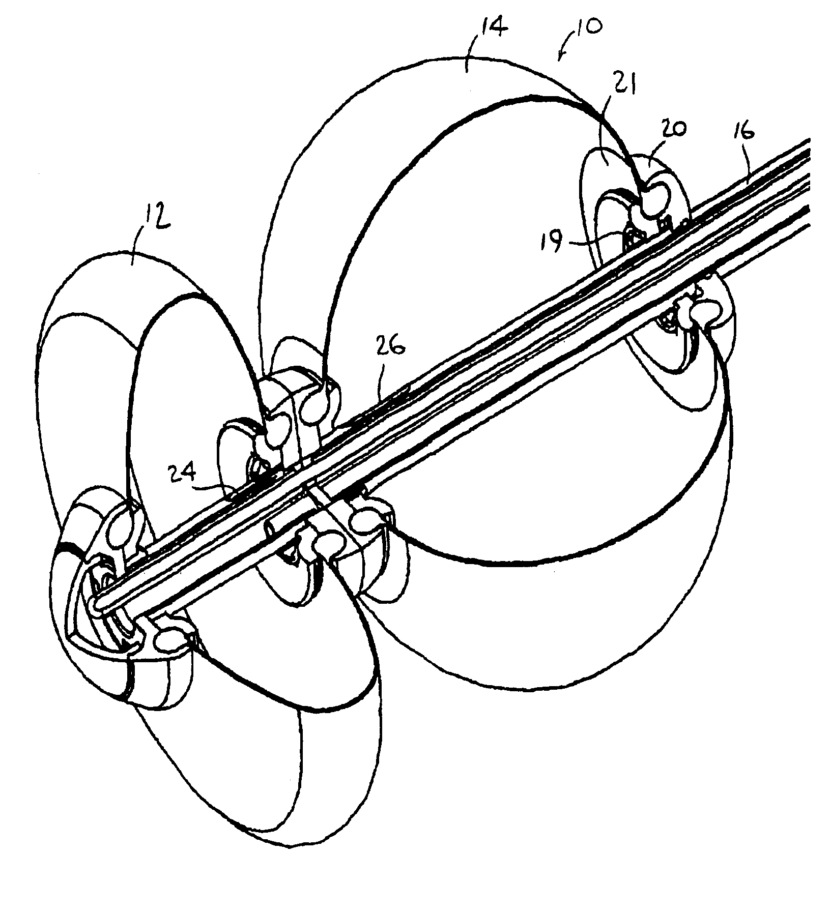
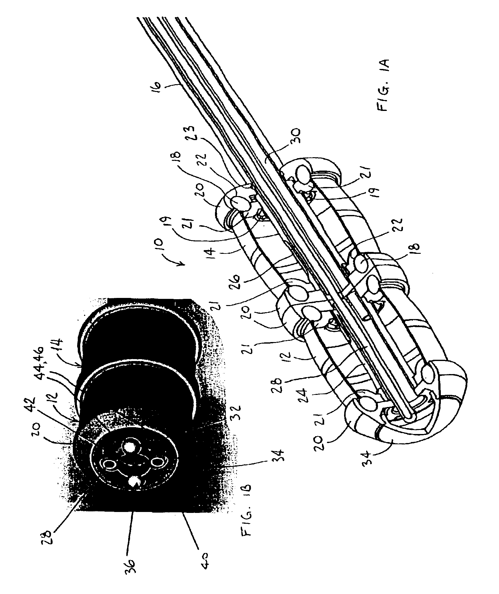
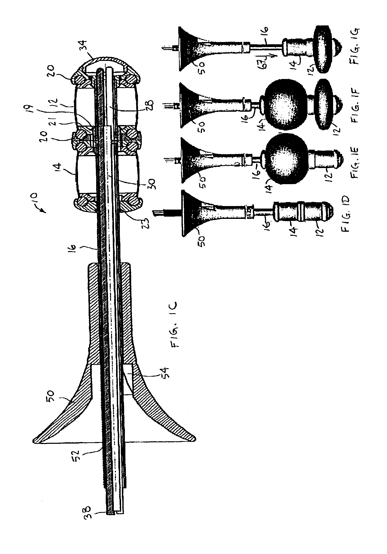
[0018]Reference is now made to FIG. 1A, which illustrates an imaging system 10, constructed and operative in accordance with a preferred embodiment of the present invention.

[0019]Imaging system 10 may comprise first and second outwardly expandable elements 12 and 14. One of the outwardly expandable elements may be the proximal element and the other one may be the distal element. For example, in terms of the explanation that follows with reference to FIGS. 2-8, first element 12 is the distal element that enters the body lumen first, and second element 14 is the proximal element that enters the body lumen last.

[0020]In accordance with a preferred embodiment of the present invention, first and second expandable elements 12 and 14 expand to different shapes. First expandable element 12 may expand substantially radially with negligible axial expansion. In contrast, second expandable element 14 may expand both radially and axially, such as expanding generally spherically.

[0021]First and s...


PUM


Abstract

An imaging system comprising an imaging device assembled on a carrier tube, and a first outwardly expandable element and a second outwardly expandable element mounted on the carrier tube, wherein the second expandable element is expandable both radially and axially, the imaging system comprising a mode of operation, wherein during expansion of the second expandable element, obstruction of the radial expansion of the second expandable element causes the axial expansion of the second expandable element to propel the carrier tube and the imaging device axially.

Description

FIELD OF THE INVENTION[0001]The present invention relates generally to medical imaging systems, and particularly to a self-propelled imaging system, suitable for imaging body lumens, such as the gastrointestinal (GI) tract.BACKGROUND OF THE INVENTION[0002]Many imaging devices are known for producing medical images of body lumens, such as the gastrointestinal (GI) tract. For example, endoscopy is widely used for observing, photographing tissue, and taking specimens from lesions and the like. In a conventional method of examining a colon using an endoscope, for example, the endoscope is typically manually inserted into the colon. In this manual technique, patients may often complain of abdominal pain and distention because the colon is extended or excessively dilated, thereby necessitating stopping the endoscopic procedure. Furthermore, it is not unusual for the colon to bleed and be accidentally perforated. Insertion of an endoscope through the sigmoid colon and into the descending c...

Claims


Application Information

Patent Timeline
IPC IPC(8): A61B1/00A61B1/005A61B1/31
CPCA61B1/00082A61B1/31A61B1/0051A61B1/00156
Inventor GROSS, YOSEF
Owner G I VIEW LTD (IL)
Learn More