Eureka AIR delivers breakthrough ideas for toughest innovation challenges, trusted by R&D personnel around the world.

Vehicle occupant weight estimation apparatus

a technology for occupants and weights, applied in pedestrian/occupant safety arrangements, instruments, tractors, etc., can solve the problems of inability to accurately determine the posterior weight of occupants, the system that classifies occupants, and the detrimental effect of deployment on the safety of pedestrians, etc., to achieve accurate measurement of occupants' size and weight, and simple method. reliable

Inactive Publication Date: 2006-01-24
INTELLIGENT MECHANTRONIC SYST INC
View PDF14 Cites 7 Cited by
  • Summary
  • Abstract
  • Description
  • Claims
  • Application Information

AI Technical Summary

Benefits of technology

[0005]The present invention is based on the fact that, in an occupant classification or weight detection system, false readings due to external forces and losses due to body angle and foot position can be compensated for, if these factors can be detected and measured reliably and consistently. This invention provides a simple, reliable method of determining these factors and using them in conjunction with force / load sensors to accurately determine an occupant's size and weight.

Problems solved by technology

In such a case, deployment may even be more detrimental than no deployment at all.
A system that classifies the occupant based on the strength of an electric field (or the capacitance of the human body) may be fooled if a portion of the signal used to excite the sensor is lost.
A system that classifies the occupant based on the load distribution, size, shape and / or orientation of the occupant's posterior may not be reliable because varying people of varying heights and weights may have posteriors with similar size and shape characteristics.
A system that relies solely on force / load sensors cannot account for false readings due to external forces such as accelerations or losses due to body angle or foot position.

Method used


Image

  • Vehicle occupant weight estimation apparatus
  • Vehicle occupant weight estimation apparatus
  • Vehicle occupant weight estimation apparatus

Examples


Embodiment Construction

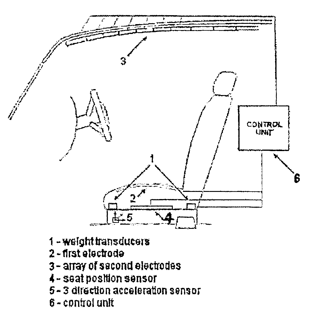
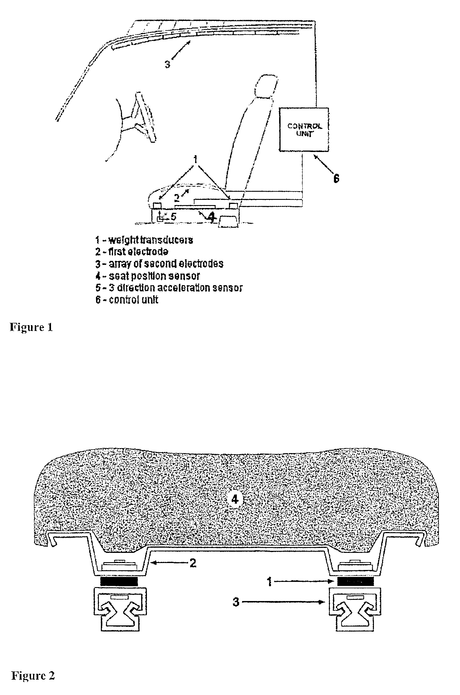
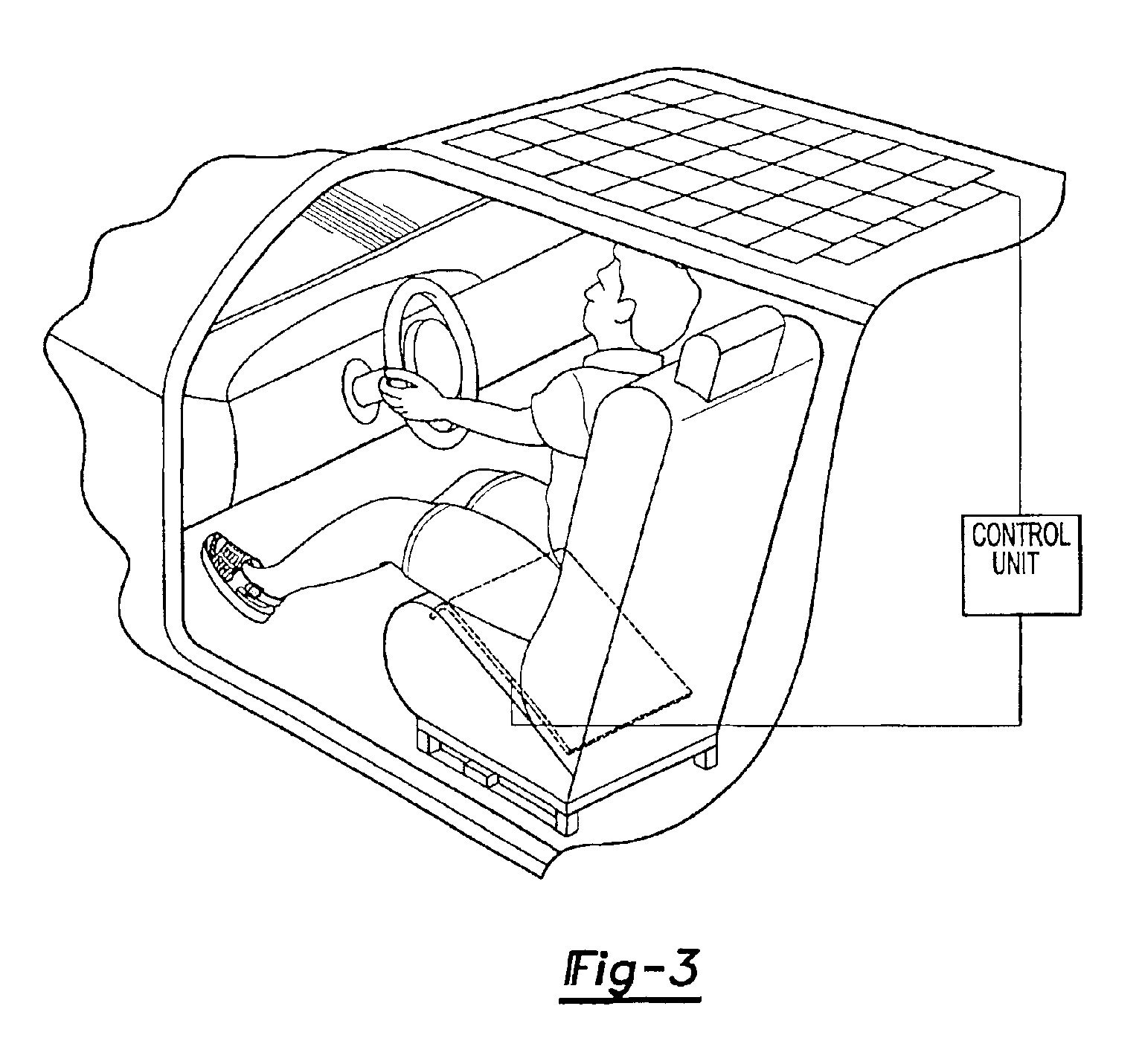
[0011]As FIG. 1 shows, the force / load sensors (1) are mounted in the four corners of the seat pan. The first electrode (2) of the head position sensor is mounted in a vehicle seat. The second electrode is an element of the array (3) mounted to the ceiling of the vehicle above the occupant's seat. A seat position sensor (4) is mounted between the seat pan and the supports. A three-direction acceleration sensor (5) is mounted rigidly under the seat. A control unit (6) continuously monitors all of the sensors. The control unit (6) utilizes an excitation method and a synchronous detection method to measure capacity. It uses a micro power low frequency signal that is safe for humans. The resulting weight measurement read by the force / load sensors is biased to account for body angle, foot position and external forces acting on the occupant.

[0012]In the preferred system, the force / load transducers measure the weight distribution on the seat pan. A weight is measured on each corner of the s...


PUM


Abstract

This invention describes an occupant size and weight detection device consisting of a combination of force / load sensors (1), a head position sensor (2, 3), a multidirectional acceleration sensor (5), and a seat position sensor (4) used to determine the weight of an occupant based on weight distribution, body angle and foot position. The goal of the invention is to determine the weight of an occupant who is sitting in the front seat of a vehicle that is subjected to the dynamic forces resulting from the vehicle moving. This technology can be used in applications such as automotive occupant weight and position sensing for use with safety devices such as airbags.

Description

[0001]This application is a 371 of PCT / IB1 / 01722, filed Sep. 19, 2001, which claimed the benefit of U.S. Provisional Applications No. 60 / 233,523, filed Sep. 19, 2000 and No. 60 / 310,259 filed Aug. 7, 2001.BACKGROUND OF THE INVENTION[0002]Vehicle occupant protection systems, which are activated in response to a vehicle crash, for the purpose of mitigating occupant injury are well known in the art. A vehicle may contain automatic safety restraint actuators such as front and side air bags, seat belt pretensioners, and deployable knee bolsters. The occupant protection system may further include a collision / crash sensor for sensing the occurrence of a vehicle crash and for providing an electrical signal indicative of the crash severity.[0003]Several known occupant protection systems include an occupant classification or weight detection system. The occupant classification / weight detection system could consist of occupant size or weight determination on force / load sensors, capacitive / elect...

Claims


Application Information

Patent Timeline
Patent Type & Authority Patents(United States)
IPC IPC(8): G01G19/08G01G19/00B60R21/01B60R21/015G01G19/414
CPCG01G19/4142B60R21/01516B60R21/01532B60R21/01554
Inventor DESROCHERS, KRISTOPHER L.JOHNSON, BRIANKARRAY, FAKHRIBASIR, OTMAN ADAMFILIPPOV, VLADIMIR
Owner INTELLIGENT MECHANTRONIC SYST INC
Why Eureka
Eureka Blog
Learn More