Detection of coolant contamination in lubricating fluids

a technology of lubricating fluid and coolant, applied in the direction of material impedance, fluid resistance measurement, instruments, etc., can solve the problems of difficult rationalization of fluid behavior, limited tracking of such effects,

Inactive Publication Date: 2006-01-24
EATON CORP
View PDF10 Cites 24 Cited by
  • Summary
  • Abstract
  • Description
  • Claims
  • Application Information

AI Technical Summary

Problems solved by technology

Although the aforesaid known technique of differential impedance spectroscopy has been found useful for monitoring changes in engine lubricant due to the effect of products of combustion, it has not be found limited to tracking such effects.
The aforesaid technique is described in U.S. Pat. No. 6,278,281 although useful, has not been found satisfactory for detecting the presence of coolant in the engine lubricant and it has been found quite difficult to rationalize the behavior of the fluid over a range of temperatures where the amount of coolant contamination is varying due to progressive leakage into the engine lubricant.

Method used


Image

  • Detection of coolant contamination in lubricating fluids
  • Detection of coolant contamination in lubricating fluids
  • Detection of coolant contamination in lubricating fluids

Examples


Embodiment Construction

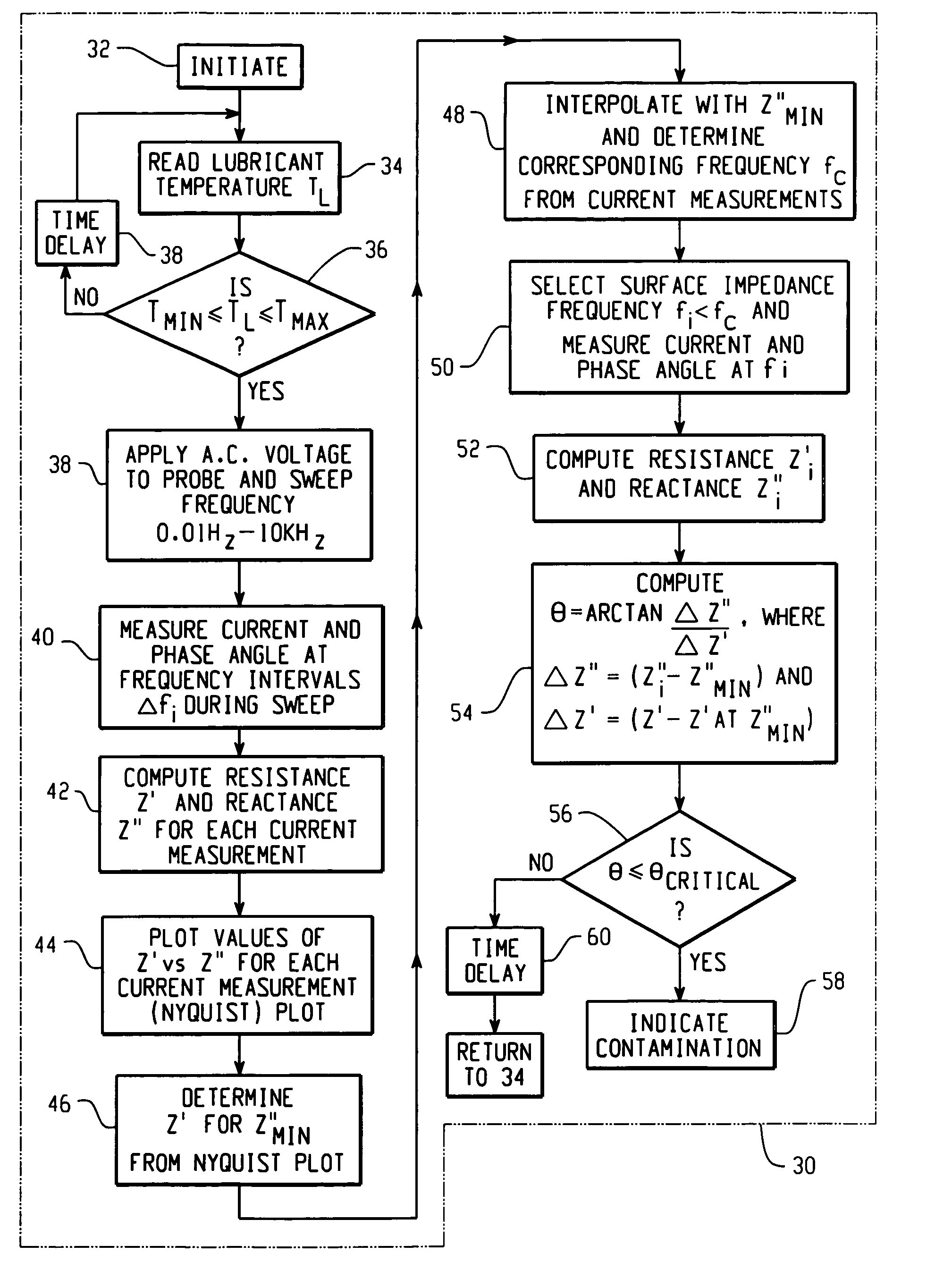
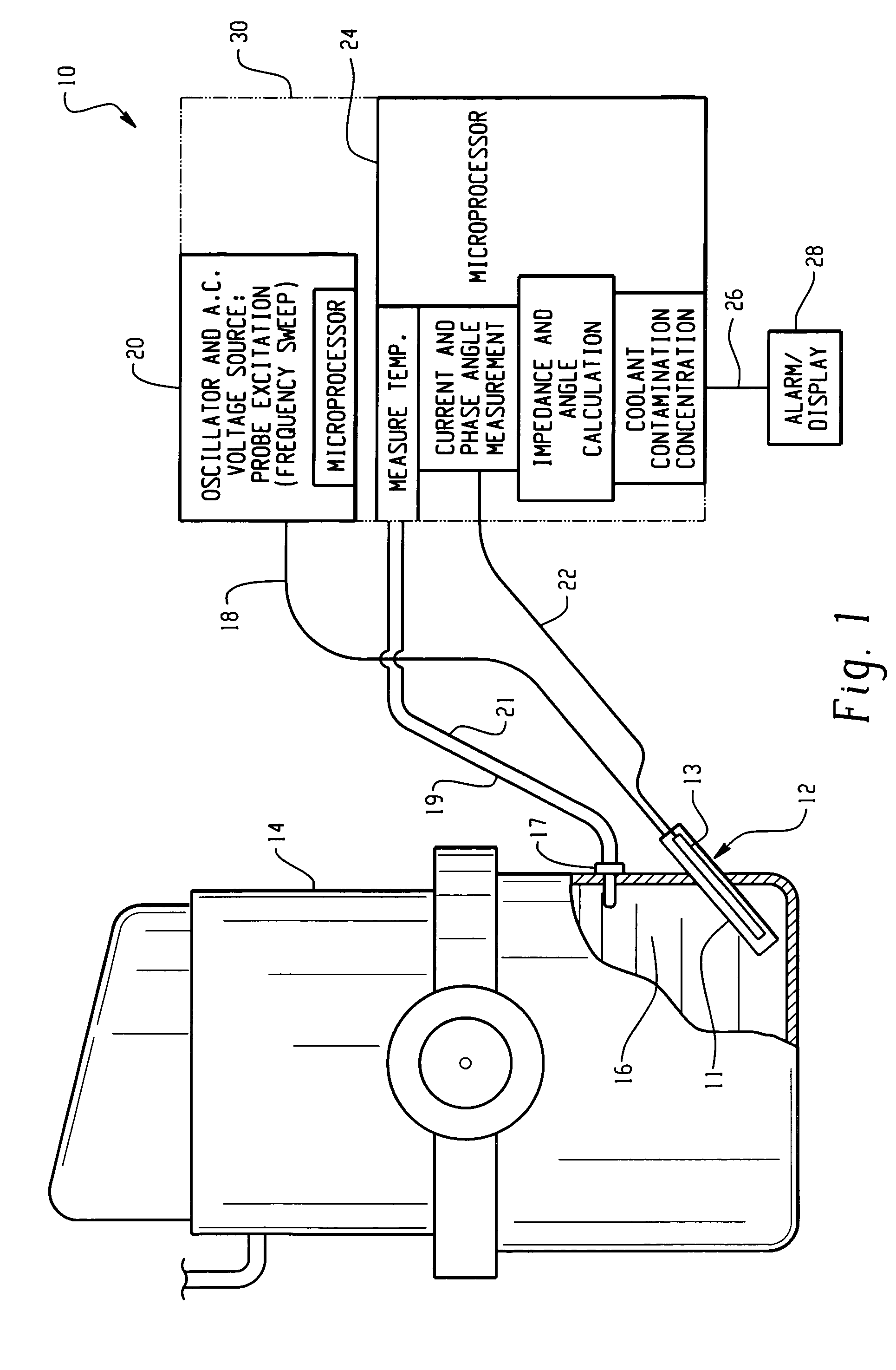
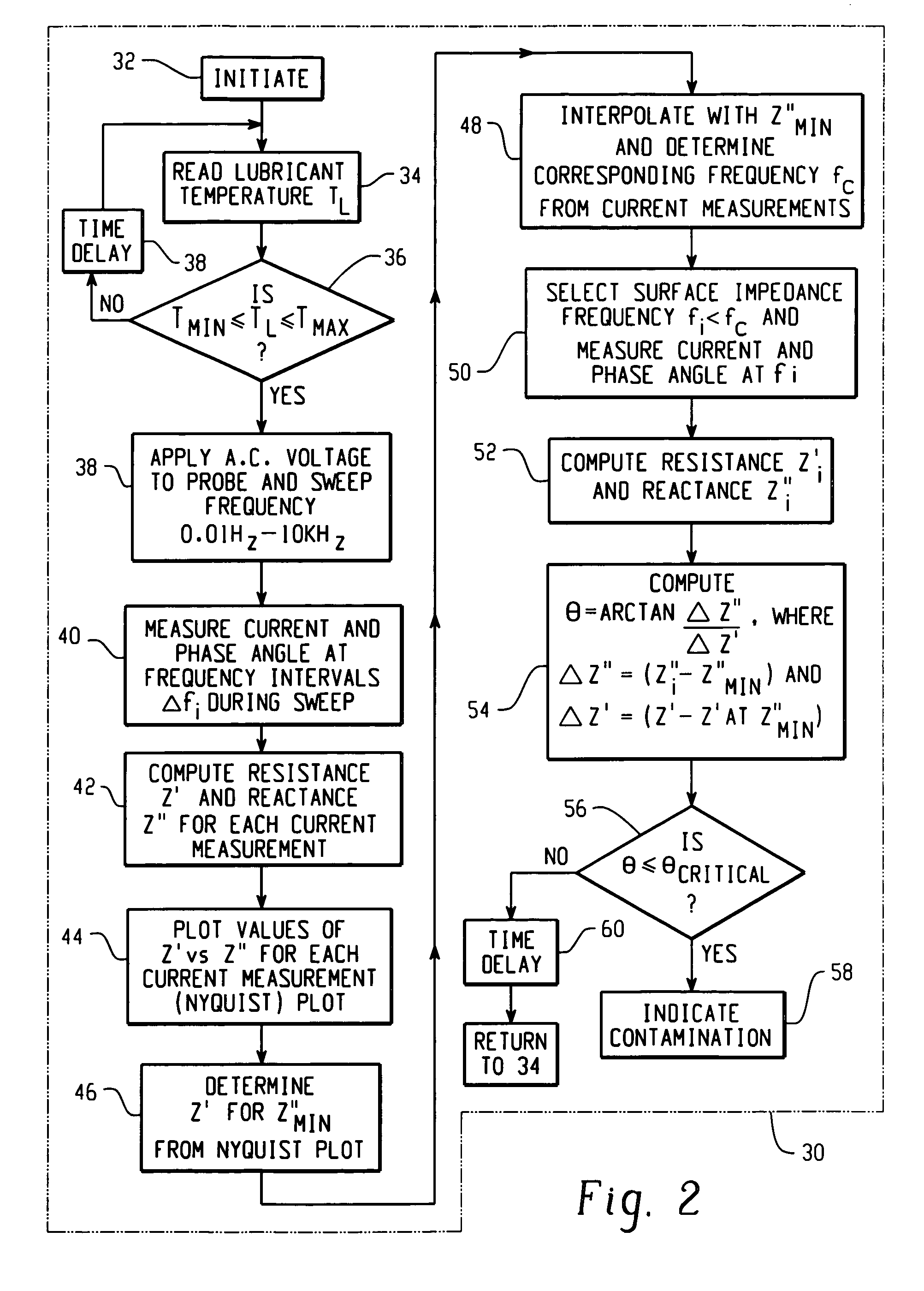
[0010]Referring to FIG. 1, the invention is indicated generally at 10 and includes a probe 12 having a pair of spaced electrodes 11, 13, which probe is inserted into the crankcase of an engine 14 and immersed in the engine lubricant indicated at 16. The probe 12 has connections for its electrodes extending externally of the engine. The probe 12 has a first electrode 11 connected to a controller 30 along line 18; and, a second probe electrode 13 is connected along line 22 to the controller. Controller 30 includes a source of low voltage alternating current indicated at 20; and, in the presently preferred practice of the invention controller 30 generates an excitation voltage in the range of about 0.01 Hz to 10 kHz. A voltage source 20 is connected along line 18 to the probe electrode 11.

[0011]Controller 30 also includes a microprocessor 24 and performs measurement of the current magnitude and the current phase angle and performs the impedance angle calculations as will be hereinafter...


PUM

PropertyMeasurementUnit
angleaaaaaaaaaa
frequencyaaaaaaaaaa
voltageaaaaaaaaaa

Abstract

An impedance spectroscopy technique and system for detecting in real time engine coolant contamination in lubricant. A probe is disposed in the lubricant and the probe excited with an a.c. voltage frequency sweep over a selected frequency range. The current and current phase angle are measured at selected frequency intervals and the reactance and resistance computed and plotted at each frequency internal as Nyquist plots. The Nyquist minimum is determined at various lubricant temperatures and a database compiled. The probe is then excited in-situ and current measurements taken for a selected frequency lower than the Nyquist minimum to insure measurement of electrode surfaces characteristics. The reactance and resistance are then computed and the angle Θ of change (slope) of reactance with respect to resistance computed. The value of Θ is then compared with values of contamination concentration Ψ versus Θ in a database, and the value of Ψ determined by interpolation.

Description

BACKGROUND OF THE INVENTION[0001]The present invention relates to the employment of impedance spectroscopy to determine the chemical condition of lubricating fluids as, for example the condition of lubricants used in an internal combustion engine.[0002]A known technique for monitoring in real time the condition of engine lubricant is described in U.S. Pat. No. 6,278,281 assigned to the assignee of the present invention and which describes using the differential of current measurements or impedance for separate current measurements taken at high and low frequencies indicative respectively of bulk fluid and electrode surface impedance. Such differential impedance spectroscopy has proven to be a useful technique for enabling a transducer to provide a continuous signal indicative of the engine lubricant during operation of the engine.[0003]However, it has been found that there is also the need to readily identify the presence of any engine coolant leaking from the engine coolant system ...

Claims


Application Information

Patent Timeline
Patent Type & Authority Patents(United States)
IPC IPC(8): G01R27/22G01R23/16G01R27/26G01N27/06G01N33/28
CPCG01N33/2888G01N27/06
Inventor SOSNOWSKI, DAVID R.HIRTHE, RICHARD W.
Owner EATON CORP
Why Eureka
Try Eureka