Adaptive antenna for use in wireless communication systems

a wireless communication system and adaptive antenna technology, applied in the field of adaptive antennas for wireless communication systems, can solve problems such as interference, multi-path fading, radio frequency signals transmitted from senders, stations or mobile subscriber units, etc., to increase the capacity of a cell, increase the effective transmit power, and increase the data rate

Inactive Publication Date: 2006-01-24
IPR LICENSING INC
View PDF23 Cites 19 Cited by
  • Summary
  • Abstract
  • Description
  • Claims
  • Application Information

AI Technical Summary

Benefits of technology

[0013]The intercell interference problem is exacerbated in CDMA systems, since the subscriber units in adjacent cells may typically be transmitting on the same frequency. What is needed is a way to reduce the subscriber unit antenna's apparent field of view, which can have a marked effect on the operation of the forward link (base to subscriber unit or access point to client station) by reducing the apparent number of interfering transmissions. A similar improvement is needed for the reverse link, so that the transmitted signal power needed to achieve a particular receive signal quality could be reduced.
[0015]The present invention provides a precise mechanism for determining in which direction the base station or access point assigned to the mobile subscriber unit or client station, respectively, is located and provides a means for configuring the antenna apparatus to maximize the effective radiated and / or received energy. The antenna apparatus includes at least one active antenna element that transmits and receives RF energy, multiple passive antenna elements that re-radiate the RF energy, and a like number of selective impedance components, each respectively coupled to one of the passive antenna elements. The selectable impedance components are independently adjustable (i.e., programmable) to affect the direction of the beam produced by the directive antenna. Thus, forward and reverse links have improved gain.
[0018]Through the use of an array having at least one active antenna element and multiple passive antenna elements each having a programmable re-radiation phase, the antenna apparatus is estimated to increase the effective transmit power per bit transmitted by as much as 3 decibels (dB) for reverse link communications over classic phased array antenna configurations, which provide 4.5 dBi. Thus, the number of active subscriber units or client stations in a cell may remain the same while the antenna apparatus of this invention increases data rates for each subscriber unit or client station beyond those achievable by prior art antennas. Alternatively, if data rates are maintained at a given rate, more subscriber units or client stations may be active at the same time in a single cell using the antenna apparatus described herein. In either case, the capacity of a cell is increased, as measured by the sum total of data being communicated at any moment in time.

Problems solved by technology

Various problems are inherent in prior art antennas used on mobile subscriber units in wireless communications systems, such as CDMA cellular systems, and client stations in Wireless Local Area Network (WLAN) systems, e.g., 802.11 systems.
One such problem is called multipath fading.
In multipath fading, a radio frequency signal transmitted from a sender (either base station or mobile subscriber unit) may encounter interference on route to an intended receiver.
This results in fading or dropouts in the received signal, hence the term multipath fading.
Single element antennas are highly susceptible to multipath fading.
A single element antenna has no way of determining the direction from which a transmitted signal is sent and cannot be tuned or attenuated to more accurately detect and receive a signal in any particular direction.
The dual element antenna described in the aforementioned reference is also susceptible to multipath fading, due to the symmetrical nature of the hemispherical lobes formed by the antenna pattern when the phase shifter is activated.
Another problem present in cellular communication systems is intercell interference.

Method used


Image

  • Adaptive antenna for use in wireless communication systems
  • Adaptive antenna for use in wireless communication systems
  • Adaptive antenna for use in wireless communication systems

Examples


Embodiment Construction

[0044]A description of preferred embodiments of the invention follows.

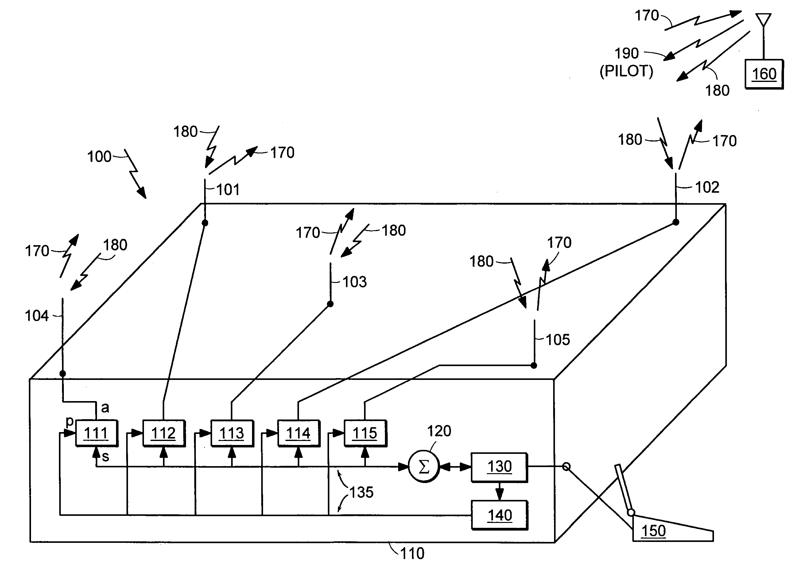
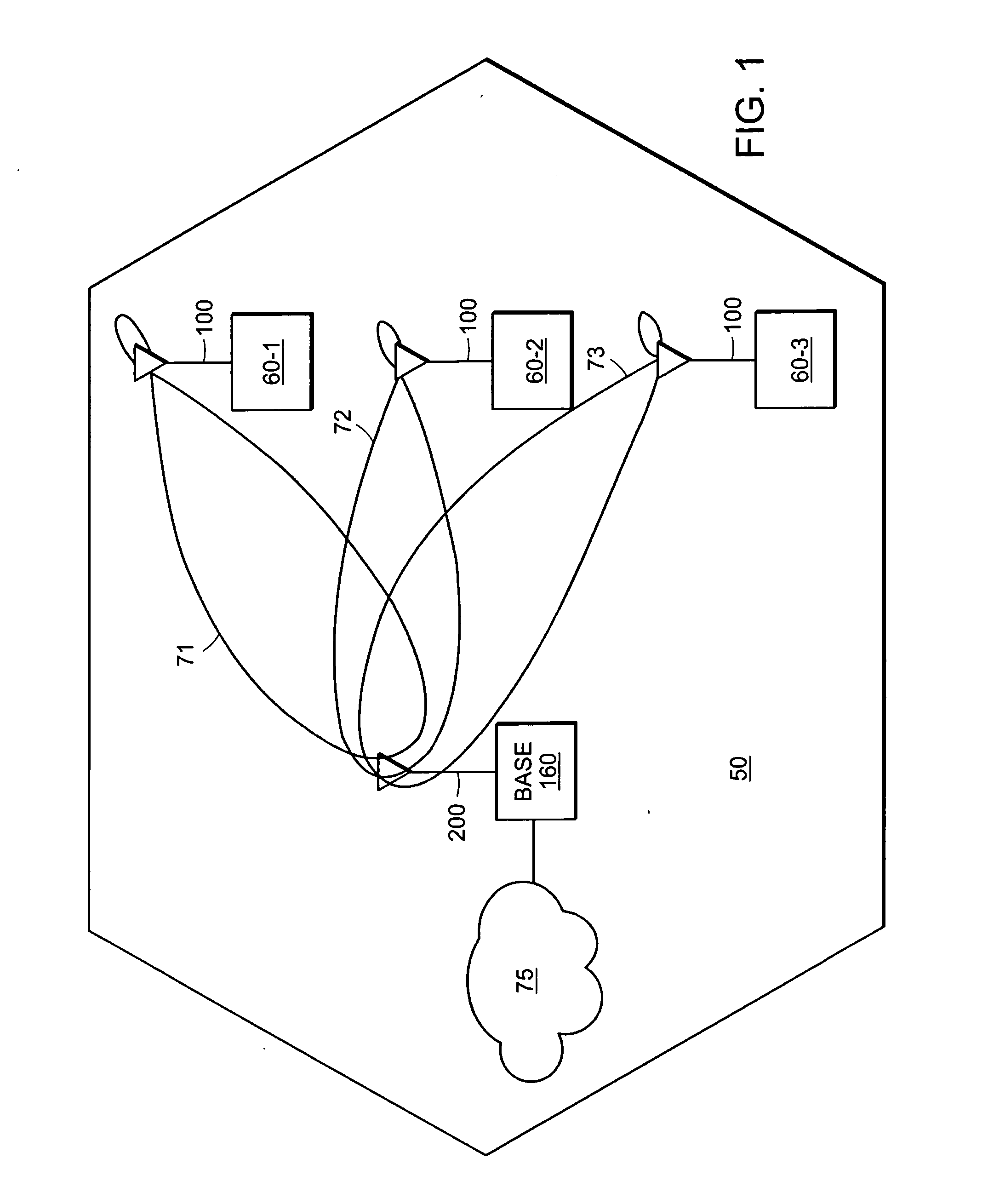
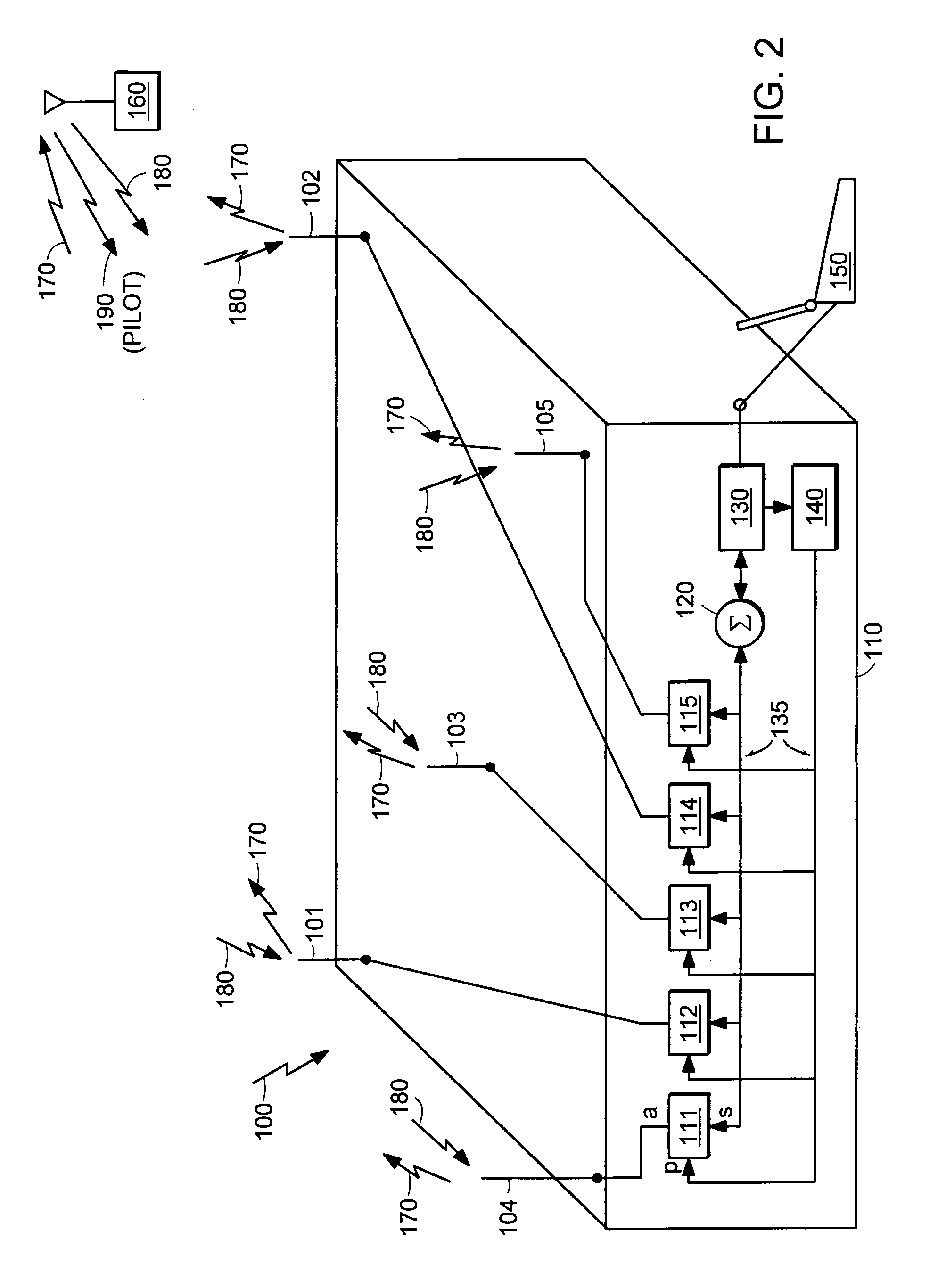
[0045]FIG. 1 illustrates one cell 50 of a typical CDMA cellular communication system or a Wireless Local Area Network (WLAN), such as an 802.11 network. In a CDMA cellular communication system, the cell 50 represents a geographical area in which mobile subscriber units 60-1 through 60-3 communicate with centrally located base station 160. In the WLAN, the cell represents a geographical area in which client stations 60-1 through 60-3 communicate with a centrally located Access Point (AP) 160. For purposes of illustrating the principles of the present invention, the embodiment disclosed is that of a CDMA cellular communication system; however, the principles apply similarly to a WLAN unless otherwise specified. Thus, it should be understood that descriptions of a base station 160 apply to an access point 160 and descriptions of mobile subscriber units 60-1 through 60-3 apply to client stations 60-1 through 60-3. The...


PUM


Abstract

An antenna apparatus, which can increase capacity in a cellular communication system or Wireless Local Area Network (WLAN), such as an 802.11 network, operates in conjunction with a mobile subscriber unit or client station. At least one antenna element is active and located within multiple passive antenna elements. The passive antenna elements are coupled to selectable impedance components for phase control of re-radiated RF signals. Various techniques for determining the phase of each antenna element are supported to enable the antenna apparatus to direct an antenna beam pattern toward a base station or access point with maximum gain, and, consequently, maximum signal-to-noise ratio. By directionally receiving and transmitting signals, multipath fading is greatly reduced as well as intercell interference.

Description

RELATED APPLICATION(S)[0001]This application is a Continuation-In-Part of U.S. application Ser. No. 10 / 441,977 filed May 20, 2003 now abandoned, entitled “Adaptive Antenna for Use in Wireless Communication Systems,” which is a Divisional of U.S. application Ser. No. 09 / 859,001, filed on May 16, 2001, now U.S. Pat. No. 6,600,456, issued Jul. 29, 2003, which claims the benefit of U.S. Provisional Application No. 60 / 234,485, filed on Sep. 22, 2000, and is a Continuation-In-Part of U.S. patent application Ser. No. 09 / 579,084 filed on May 25, 2000, now U.S. Pat. No. 6,304,215, which is a Divisional of U.S. application Ser. No. 09 / 210,117, filed on Dec. 11, 1998, now issued U.S. Pat. No. 6,100,843, which is a continuation of U.S. patent application Ser. No. 09 / 157,736 filed on Sep. 21, 1998, now abandoned. The entire teachings of the above applications are incorporated herein by reference.FIELD OF THE INVENTION[0002]This invention relates to wireless communication systems, and more partic...

Claims


Application Information

Patent Timeline
IPC IPC(8): H01Q19/10H01Q1/24H01Q3/26H01Q19/00H01Q19/32
CPCH01Q1/241H01Q1/246H01Q3/2605H01Q19/32H01Q3/446H01Q19/26H01Q3/2611
Inventor GOTHARD, GRIFFIN K.KEEL, JR., ALTON S.SNYDER, CHRISTOPHER A.CHIANG, BINGRICHESON, JOE T.WOOD, DOUGLAS H.PROCTOR, JR., JAMES A.GAINEY, KENNETH M.
Owner IPR LICENSING INC
Why Eureka
Try Eureka